
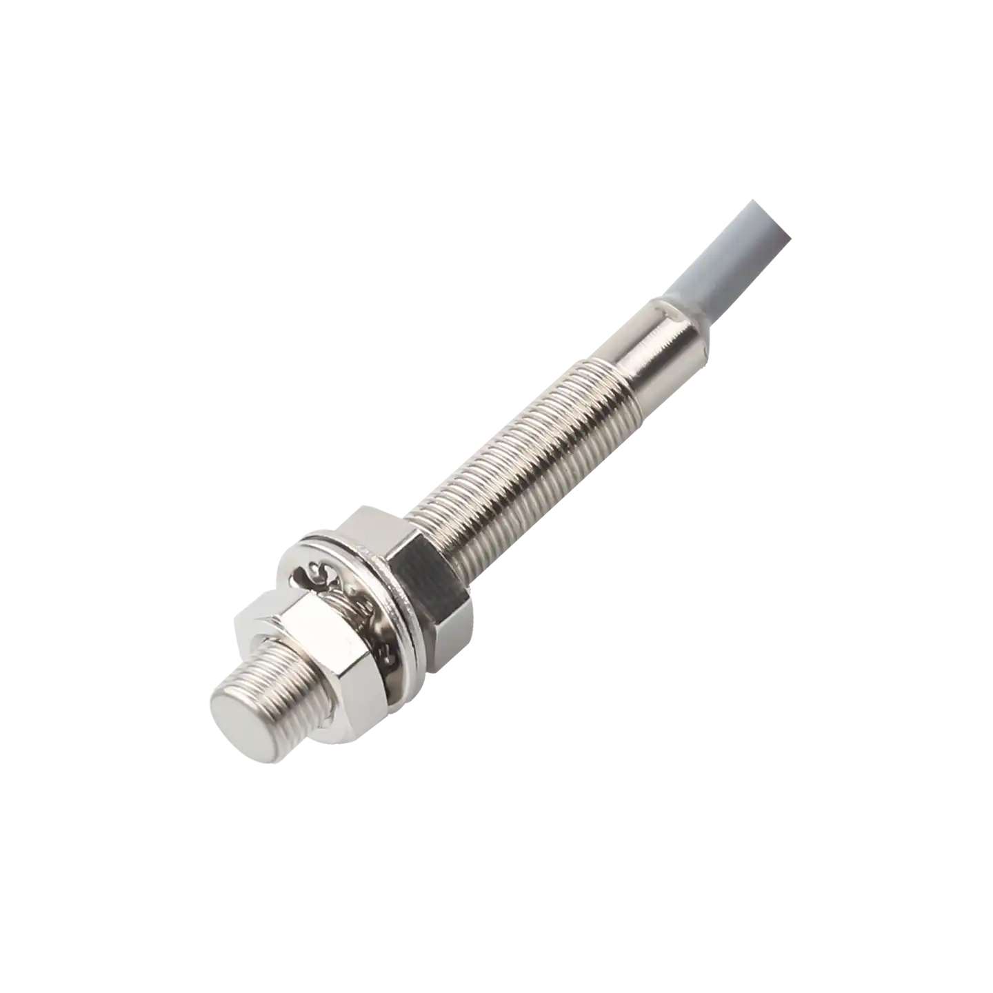
Description
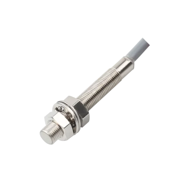
M8 cylindrical inductive sensor range
The XSZ M8 cylindrical inductive proximity sensor range is designed for non-contact detection of a metal target. The supplied range includes separate flush and non-flush versions, so mounting style and sensing distance must be selected together.
The flush reference is 1 mm ±10% with an 8 × 8 × 1 mm iron target. The non-flush reference is 2 mm ±10% with a 12 × 12 × 1 mm iron target. A different target size or metal can change the actual detection gap.
Flush and non-flush M8 configurations
These are distinct sensing configurations, not a distance setting that can be switched on a single device. Compare the specified iron target and required switching frequency as well as the nominal gap.
| Mounting version | Sensing distance | Iron standard target | Response frequency |
|---|---|---|---|
| Flush | 1 mm ±10% | 8 × 8 × 1 mm | 1 kHz |
| Non-flush | 2 mm ±10% | 12 × 12 × 1 mm | 800 Hz |
The source range notes a reduced sensing distance for non-magnetic metals. Check the actual target material, dimensions and approach path before fixing the sensing gap.
M8 series electrical and environmental data
The values below are listed for the range. Match them to the selected flush or non-flush model and its output code before wiring a controller.
Supply, output and protection
| Operating supply | 10–30 VDC; 12–24 VDC nominal (series table) |
|---|---|
| Supply ripple | 10% maximum, peak-to-peak |
| Output choices | NPN or PNP; normally open (NO) or normally closed (NC), depending on model |
| Maximum load current | 200 mA (series table; confirm selected model) |
| Residual voltage | 1.5 V maximum |
| Current consumption | 10 mA maximum |
| Listed circuit protection | Reverse supply-polarity protection (confirm selected model) |
Temperature limits
| Operating temperature | −25 to +70 °C |
|---|---|
| Storage temperature | −40 to +80 °C |
Metal-target applications and installation checks
An M8 sensor from this range can be evaluated for metal-part presence or position checks in compact machine locations. Select the mounting version and output that fit the available space, target path and control input. Verify the actual sensing gap when the metal differs from the standard iron target.
Before specifying a model
- Identify flush or non-flush installation and the iron-reference sensing distance needed.
- Confirm actual metal, target size, travel path and machine cycle against the selected frequency.
- Choose the required NPN/PNP and NO/NC model; verify its supply and permissible load.
- Obtain the dimensioned M8 drawing, cable details and exact wiring diagram.
Frequently asked questions
Is the 2 mm range available on every M8 version?
No. The supplied comparison lists 1 mm ±10% for the flush version and 2 mm ±10% for the non-flush version, each against a different iron target.
Will a non-iron metal give the same switching distance?
Do not assume that. The range notes reduced sensing distance for non-magnetic metals. Test the intended material and target size in the application.
Are NPN, PNP, NO and NC all switchable on one sensor?
They are listed as range options, but no individual model matrix is provided here. Select the exact output model needed by the controller.
What connection information is needed before installation?
Confirm the selected model’s wiring diagram, cable configuration, supply and controller input. The installation drawing must match the actual purchased version.

Reviews
There are no reviews yet.