Industrial Automation Sensing
Bring optical detection to compact machine mounts. Select the sensing mode, working distance and output for your target and installation.
Optical Detection in a Threaded Body
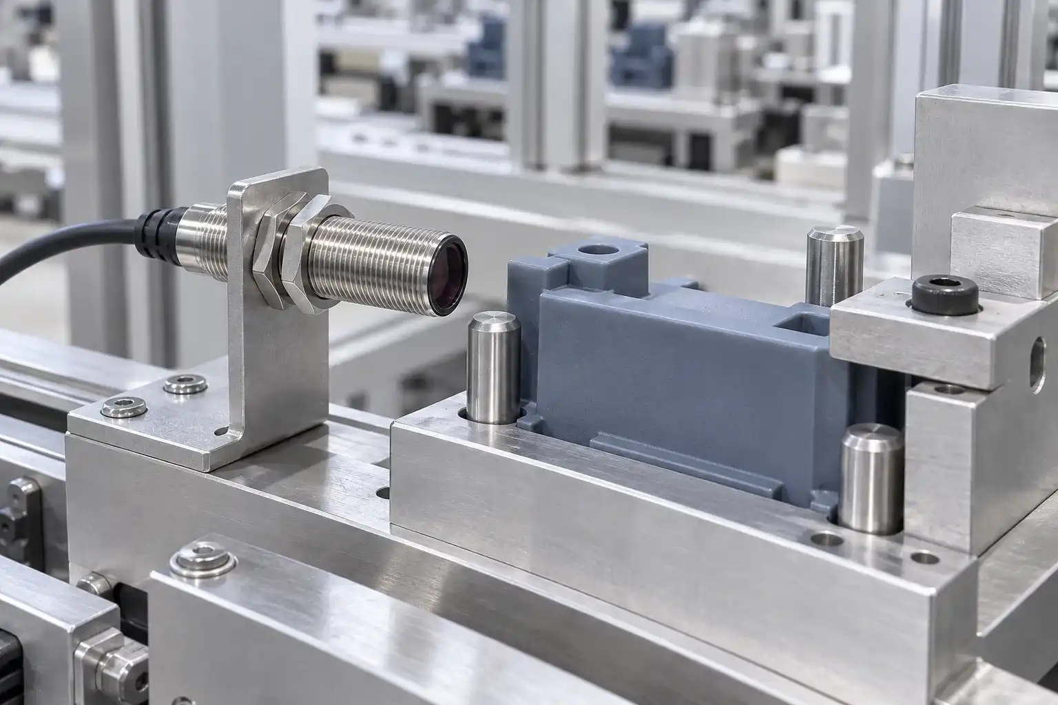
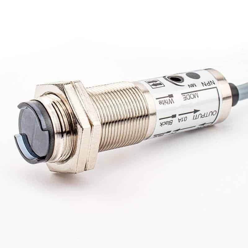
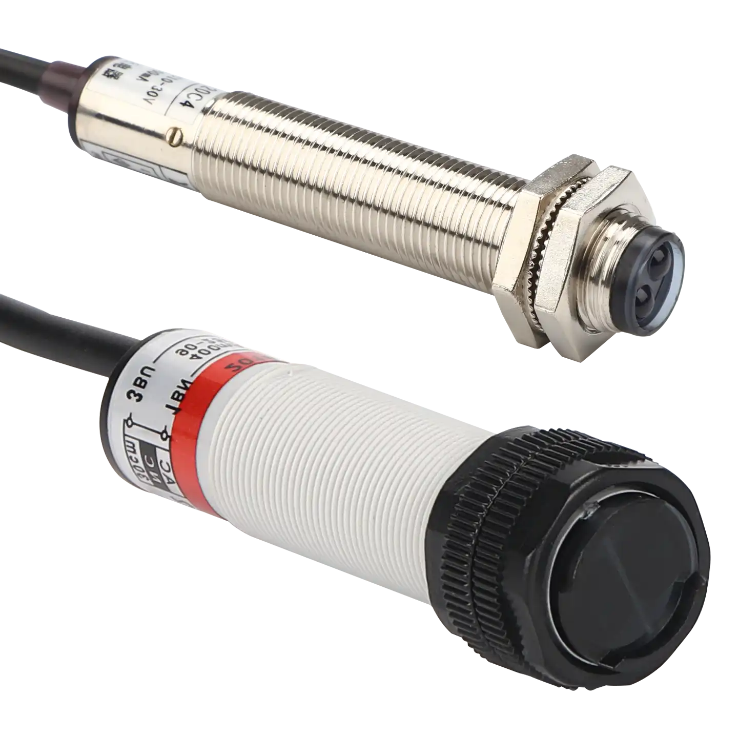
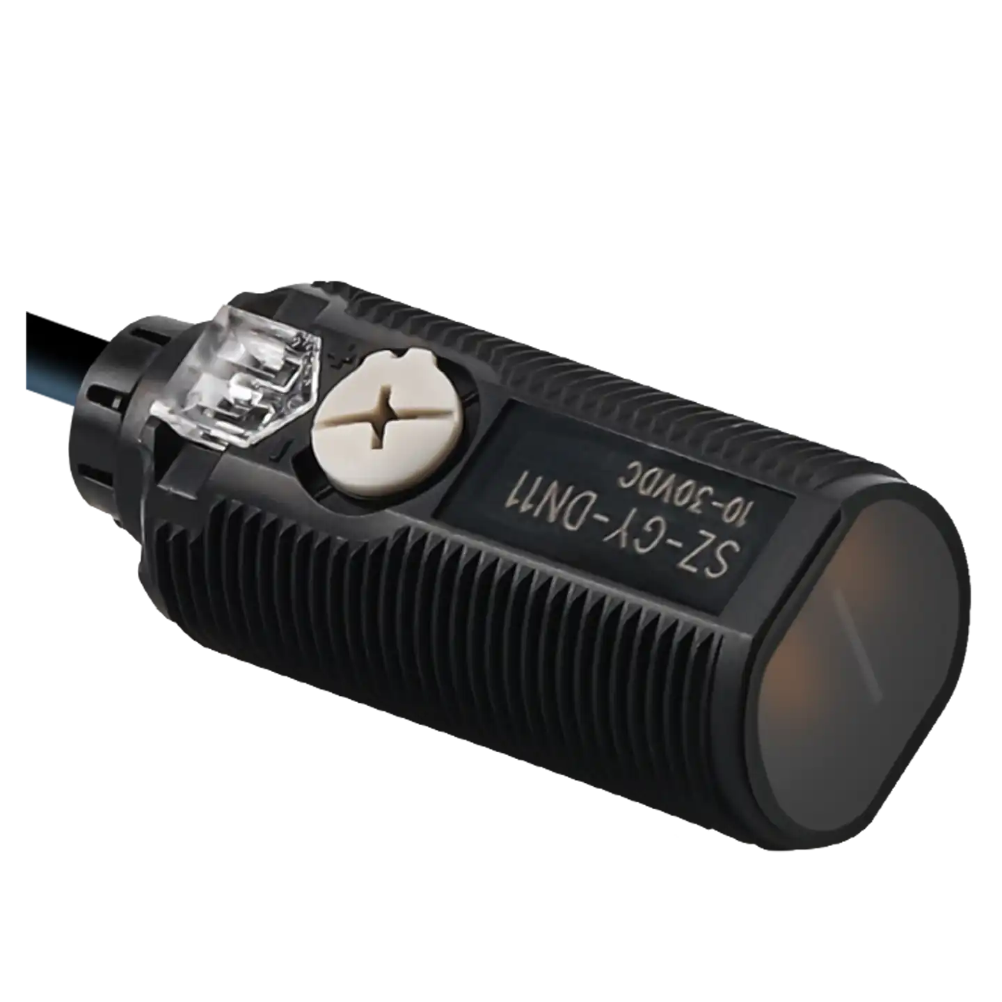
Cylindrical photoelectric sensors use light to detect objects in a round, threaded housing. Mounting nuts secure the body to a machine bracket, with the optical face aligned toward the sensing area.
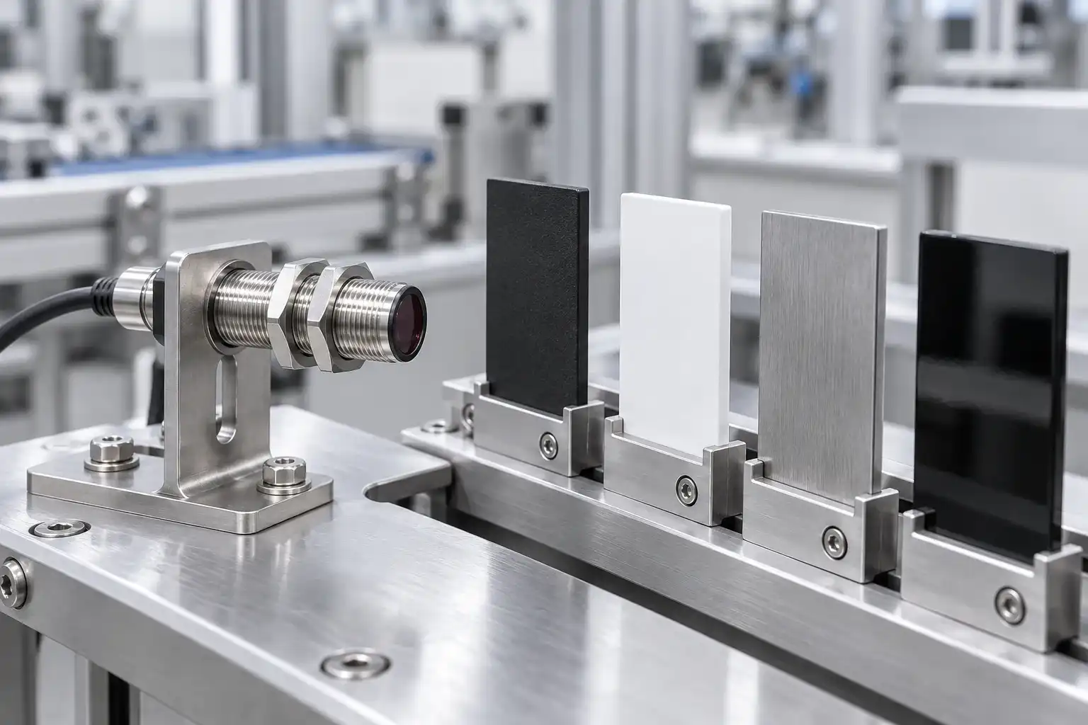
The cylindrical shape describes the housing, not the sensing principle. Choose the optical mode for the application, then check the working distance, target color and surface finish. Reflected-light detection can vary with the target, so test the actual object with enough operating margin.
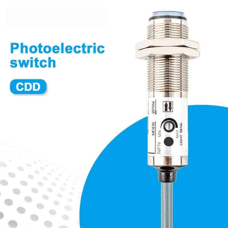
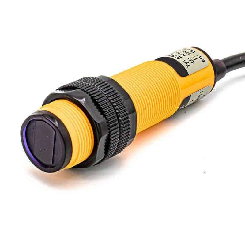
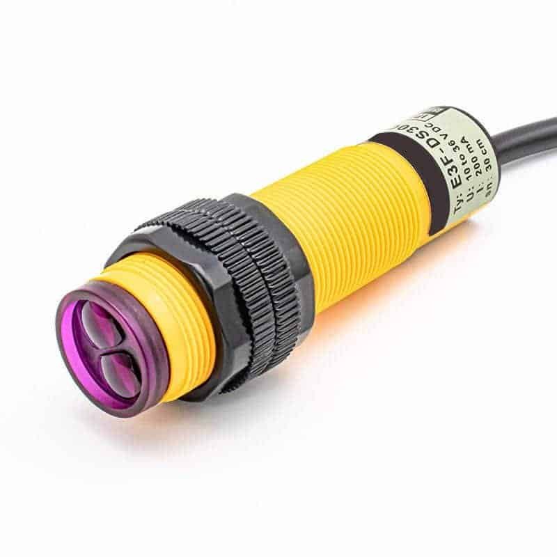
xsz sensor offers CDD metal-body models and E3F series options. Confirm the mounting thread, available depth, supply voltage, output logic and cable clearance for the selected model.
Our Product Range
Select by optical mode,
range and mounting thread.

Share the target, working distance, mounting space and controller input.
Find the right sensor for your application
Match the optical principle, working distance and threaded mounting
to your machine's object detection task.
Choose diffuse, through-beam or retro-reflective detection. Check whether the machine has room for a receiver or reflector.
Record the full working gap and target size. Test actual color, finish and transparency rather than relying on the nominal range.
Match thread size and body length to the bracket. Choose axial or radial optics to suit the beam direction and available clearance.
Verify supply voltage, output type and Light-ON or Dark-ON operation. Match response time and target spacing to the controller input.
Compare selection options at a glance
Compare sensing principles and beam directions. These options can overlap; verify each model's available configuration.
| Configuration | Main Focus | Optical Layout | Key Check | Mounting | Typical Use |
|---|---|---|---|---|---|
Diffuse- Reflective |
Reflected light |
Emitter and receiver in one body |
Surface and gap |
Single sensor, no reflector |
Carton presence, fixture checks |
Through- Beam |
Beam break |
Separate emitter and receiver |
Target opacity |
Opposing units, aligned axes |
Passing objects, part counting |
Retro- Reflective |
Return path |
Sensor and matched reflector |
Gloss and clear targets |
Sensor wired on one side |
Conveyor presence, packaging lines |
Axial Optics |
End-face beam |
Beam follows the body axis |
Front clearance |
Threaded bracket mount |
Direct-facing machine detection |
Radial Optics |
Side beam |
Beam exits across the body axis |
Beam direction |
Set body angle, then secure |
Side-facing mounting spaces |
Validate detection with real targets
Test the smallest target at both distance limits. Include changes in color, finish, angle and position.
Remove the target and check the belt, rails and background. For beam-break modes, verify the clear optical path.
Run at maximum speed and minimum spacing. Verify that the controller captures both detection and release without missed pulses.
Recheck alignment after securing the mount. Test vibration, ambient light and lens contamination under actual machine conditions.
Align the optics with your target path
Secure the threaded body, keep optics clear and verify the final switching behavior.
Arrange the optical path for the selected sensing mode.
Available options depend on the selected model.
Sinking output, when specified.
Match the controller input and load.
Sourcing output, when specified.
Check supply voltage and pinout.
Verify ON/OFF behavior against the timing diagram. Target-present logic changes with the sensing principle.
Confirm wire assignment and connection type. Allow room for routing, bending and maintenance.
Cylindrical photoelectric sensors bring optical object detection to conveyors, packaging stations and assembly fixtures. Match diffuse, through-beam or retro-reflective sensing to the target, available space and working distance.

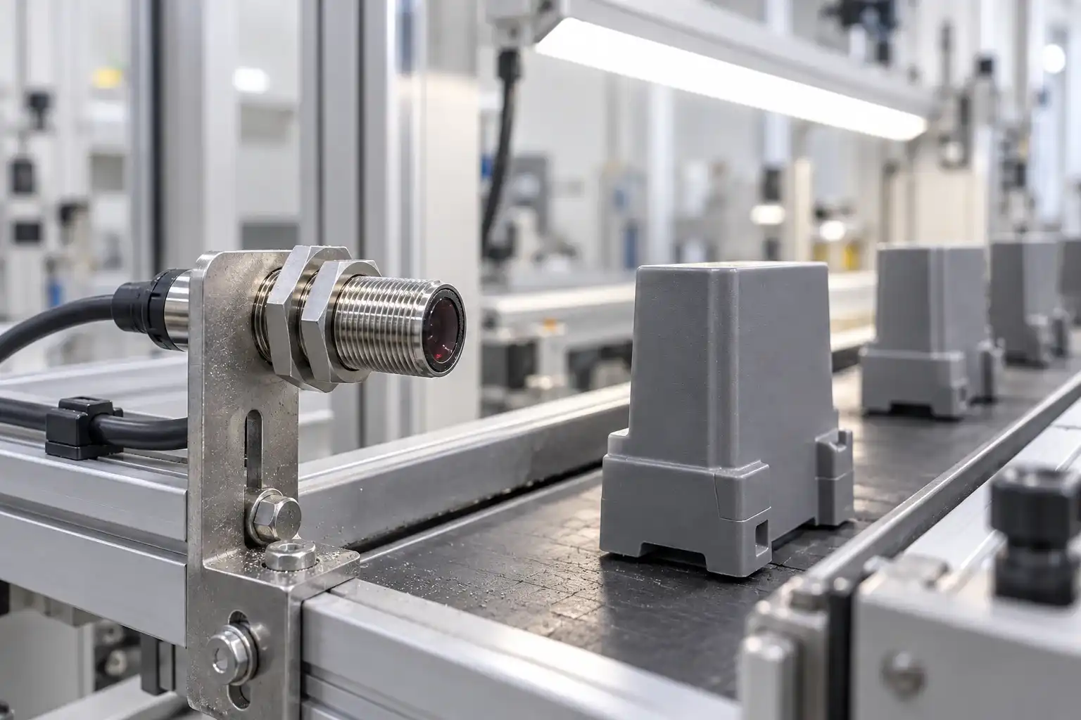
Detect cartons and opaque items at a selected point using an optical mode matched to the conveyor.

Confirm a pack or tray has reached the station before the next machine operation.

Use an aligned through-beam pair to detect individually spaced opaque parts crossing the optical path.

Check whether a workpiece is present in a fixture with a reflective model suited to its surface and gap.
Housing shape alone does not determine detection performance. Review the optical mode, target surface, installation and signal timing together.

Dark or glossy targets can change reflected-light detection. Test the least reflective surface and its angle.

Keep the emitter, receiver or reflector aligned. Allow for vibration, bracket movement and cable routing.

Test with the target removed. Belts, rails or nearby surfaces may return light to a diffuse sensor.

Keep lenses clear and test nearby lighting. Confirm blocked and clear intervals at the actual line speed.
Application review, production support and quality checks for your industrial sensing project.
A cylindrical body fits a round mounting hole or bracket, but the optical arrangement still needs to suit the machine. Consider the target surface, working gap and whether there is space for an opposing receiver or reflector.
Bring XSZ your sample, installation drawing and controller requirements. Review optical mode, beam orientation, mounting dimensions and electrical connection together before selecting a configuration for repeat supply.
Validate the actual target and installation. Confirm the signal when the target is present, absent and moving at production speed.
Review target size and surface, optical mode, working distance, mounting space and controller input.
Confirm housing, beam orientation, connection and the functional checks required for the selected model.
Discuss repeat orders and project-specific requirements, then confirm the supported configuration before production.
Production support for your selected configuration.
Match optical mode, target and mounting.
Agree the functional checks for your order.
Evaluate on the actual machine before rollout.
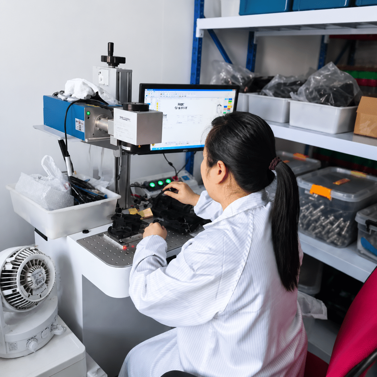
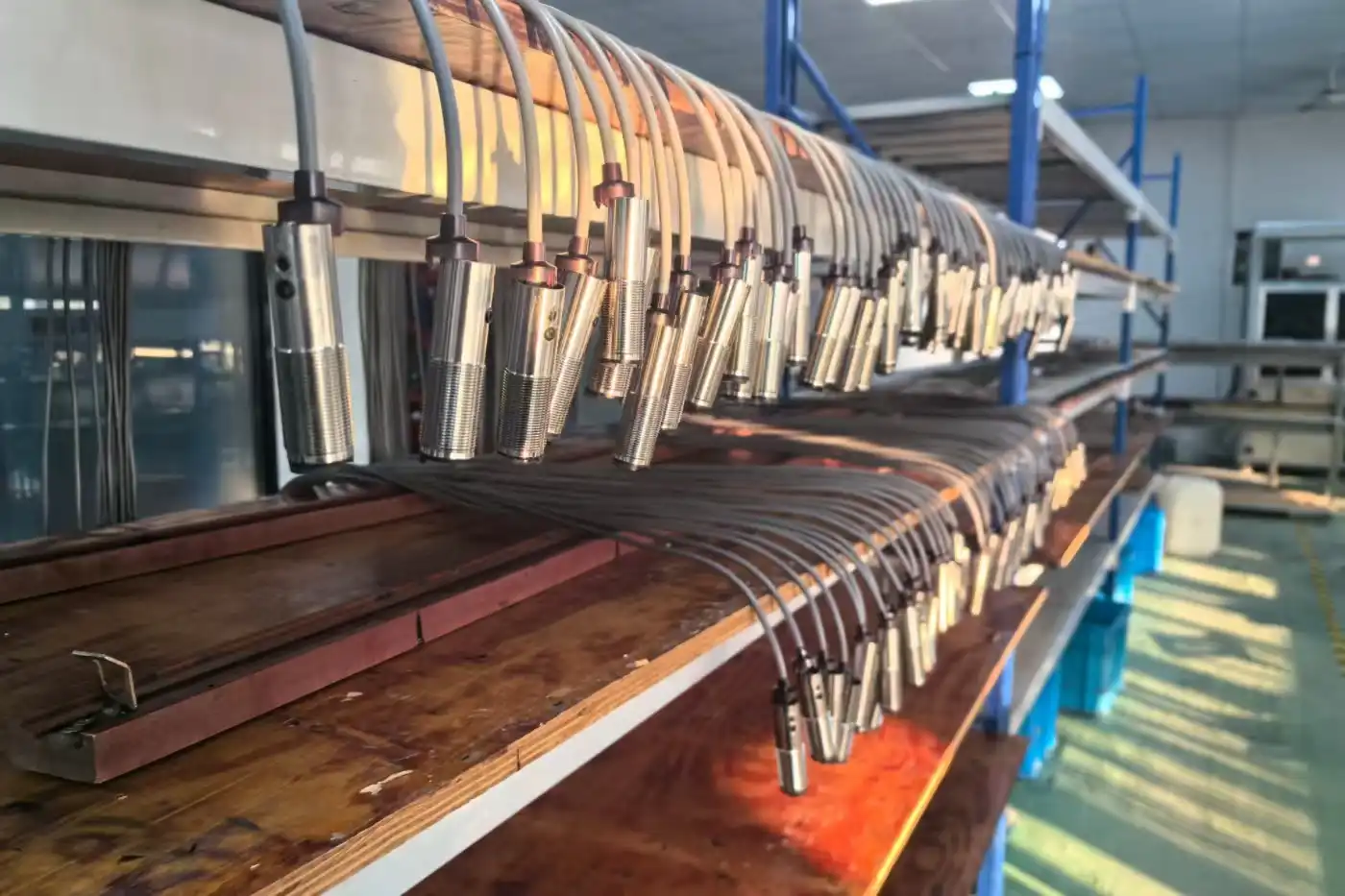
A closer look at our workstations, components and supply preparation.






Flexible Solutions for Your Application
Share your target, working distance and mounting requirements. Our engineering team can review feasible configuration and branding options for your cylindrical photoelectric sensor application.
Housing & Mounting
Review the mounting thread, body length and bracket clearance for your installation.
Sensing Mode
Discuss the optical mode and working distance for your target, background and available space.
Cable Length
Discuss cable length and routing for your machine layout.
Connection Type
Review available cable or connector options against your wiring requirements.
Output & Logic
Match the available output, switching logic and response performance to your controller.
Label / Branding
Discuss custom labels, logos and part numbers for your OEM project.
Explore More
Practical reading for cylindrical sensor selection, optical detection and installation.
Selection Guide
How to Choose a Cylindrical Photoelectric Sensor
Review the sensing mode, working distance, mounting thread and controller requirements.
Read ArticleSensor Comparison
Diffuse vs. Retro-Reflective vs. Through-Beam Sensors
Compare the optical layouts and installation needs before choosing a sensing mode.
Read ArticleApplication Guide
Photoelectric Sensor Alignment and Troubleshooting
Check optical alignment, target conditions, wiring and contamination when detection is unstable.
Read ArticleCommon Questions
Quick answers to help you select and install a cylindrical photoelectric sensor.
No. Cylindrical describes the body shape. Confirm the selected model's optical principle, working distance and installation requirements separately.
Diffuse sensing receives light reflected by the target. Retro-reflective sensing uses a reflector opposite the sensor. Through-beam sensing uses separate emitter and receiver units; the target interrupts their beam. Check which modes are available for the selected model.
Yes, especially with diffuse sensing. Target size, color, gloss and angle can change the returned light. Test the actual object and background with enough operating margin.
Confirm the thread, bracket fit, body length and cable clearance. Follow the model's tightening instructions. Align the optical face, receiver or reflector as required, then verify switching throughout the target's movement.
Check the model's supply voltage, wiring diagram and available output against the controller input. Confirm switching logic and response requirements; housing shape alone does not establish electrical compatibility.
Check alignment, a loose bracket, dirty optics, target variation and background reflections. Also check supply and wiring. Re-test target-present and target-absent states under actual operating conditions.
Let's Build a Smarter Tomorrow
Share your target, working distance, mounting space and controller requirements. Our technical team can help you review the optical mode and installation.