

Description
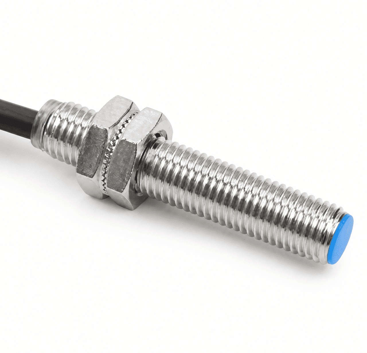
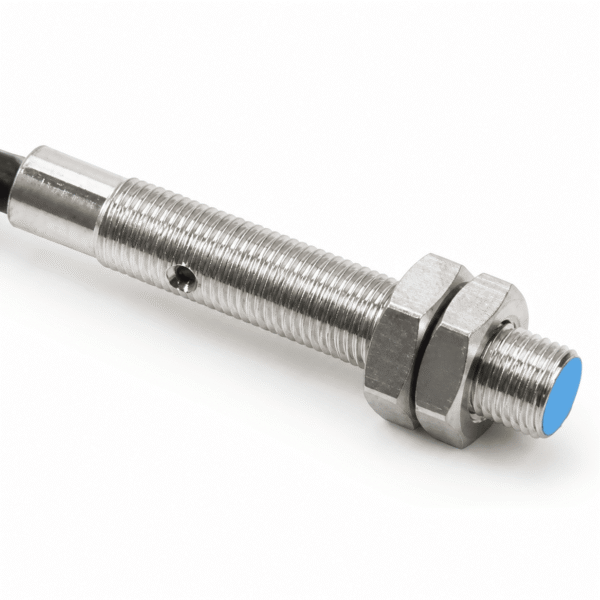
M5 magnetic switch overview
The XSZ M5 magnetic proximity switch range has a listed 10 mm ±10% sensing distance and a 0–8 mm setting distance. Its standard reference target is an Ø8 × 2 mm magnet. Separate DC two-wire models provide normally open (NO) and normally closed (NC) outputs.
Choose the output logic that matches the controller, then check the actual magnet, mounting gap, power supply and wiring for the selected model. The listed sensing distance is a reference value, not a guarantee for every magnet or installation.
| Body designation | M5 |
|---|---|
| Listed sensing distance | 10 mm ±10% |
| Setting distance | 0–8 mm |
| Output choices | DC two-wire NO and NC models |
10 mm sensing with a magnet target
The 10 mm value is the listed sensing distance, while 0–8 mm is the setting-distance range. The standard reference target is an Ø8 × 2 mm magnet. A different magnet size, strength or orientation may change the usable gap.
Plan the mounting position around the actual magnet and verify the switching point across the full motion of the equipment. Hysteresis is listed as less than 10% of the sensing distance; check the current datasheet and application test before relying on a precise repeat-switching point.
Technical specifications
Sensing and construction
| Product category | Magnetic proximity switch |
|---|---|
| Body designation | M5; confirm full dimensions on the current drawing |
| Shielding type | Shielded |
| Sensing distance | 10 mm ±10% |
| Setting distance | 0–8 mm |
| Standard target | Ø8 × 2 mm magnet |
| Hysteresis | Less than 10% of sensing distance |
| Housing / sensing face | Nickel-plated brass / ABS |
| Protection class | IP67 (IEC) |
Electrical and environmental data
| Model arrangement | Separate DC two-wire NO and NC models |
|---|---|
| Continuous load current | 50 mA in the M5 model table; verify for the chosen code |
| Operating and storage temperature | −30 to +65 °C; no freezing or condensation |
| Operating and storage humidity | 35–95% RH |
| Insulation resistance | At least 50 MΩ at 500 VDC, between energized parts and housing |
| Withstand voltage | 1,000 VAC, 50/60 Hz for 1 minute, between energized parts and housing |
Check the selected model’s supply and load ratings on its current datasheet before finalizing the controller connection.
NO and NC M5 model options
These are two independent DC two-wire model codes. Select the required output state; the two codes are not field-selectable modes of one switch.
| Output | Wiring type | Model |
|---|---|---|
| Normally open (NO) | DC two-wire | LG5A3-10-Z/EX |
| Normally closed (NC) | DC two-wire | LG5A3-10-Z/DX |
Installation and selection checks
For a magnet-position sensing point, check that the moving magnet passes the sensing face at a repeatable gap within the intended setting range. Use the current dimensional drawing to confirm overall length, mounting clearance and cable exit.
Before specifying an M5 model
- Choose the NO or NC code to match the controller input and required switching state.
- Test the actual magnet’s size, strength, orientation and travel against the 0–8 mm setting range.
- Verify the chosen model’s supply voltage, load-current limit and complete two-wire connection diagram.
- Confirm the mounting dimensions, cable arrangement, ambient conditions and switching speed required by the application.
Frequently asked questions
Is M5 the sensing distance?
No. M5 is the body designation. The listed sensing distance is 10 mm ±10%, with a 0–8 mm setting-distance range.
Which magnet is the reference target?
An Ø8 × 2 mm magnet is the standard reference target. Confirm performance with the actual magnet and installation gap.
Are NO and NC available on one switch?
No. LG5A3-10-Z/EX is the listed NO model and LG5A3-10-Z/DX is the listed NC model. Choose the required code when ordering.
What should be checked before wiring?
Check the selected model’s supply voltage, load-current limit and complete two-wire connection diagram before connecting it to the controller.
Reviews
There are no reviews yet.