M5 Series
Industrial Automation Sensing
Non-contact detection of magnet-equipped targets for machine position feedback. Choose the housing, operating gap and electrical version to suit your installation.
Position Feedback from a Target Magnet
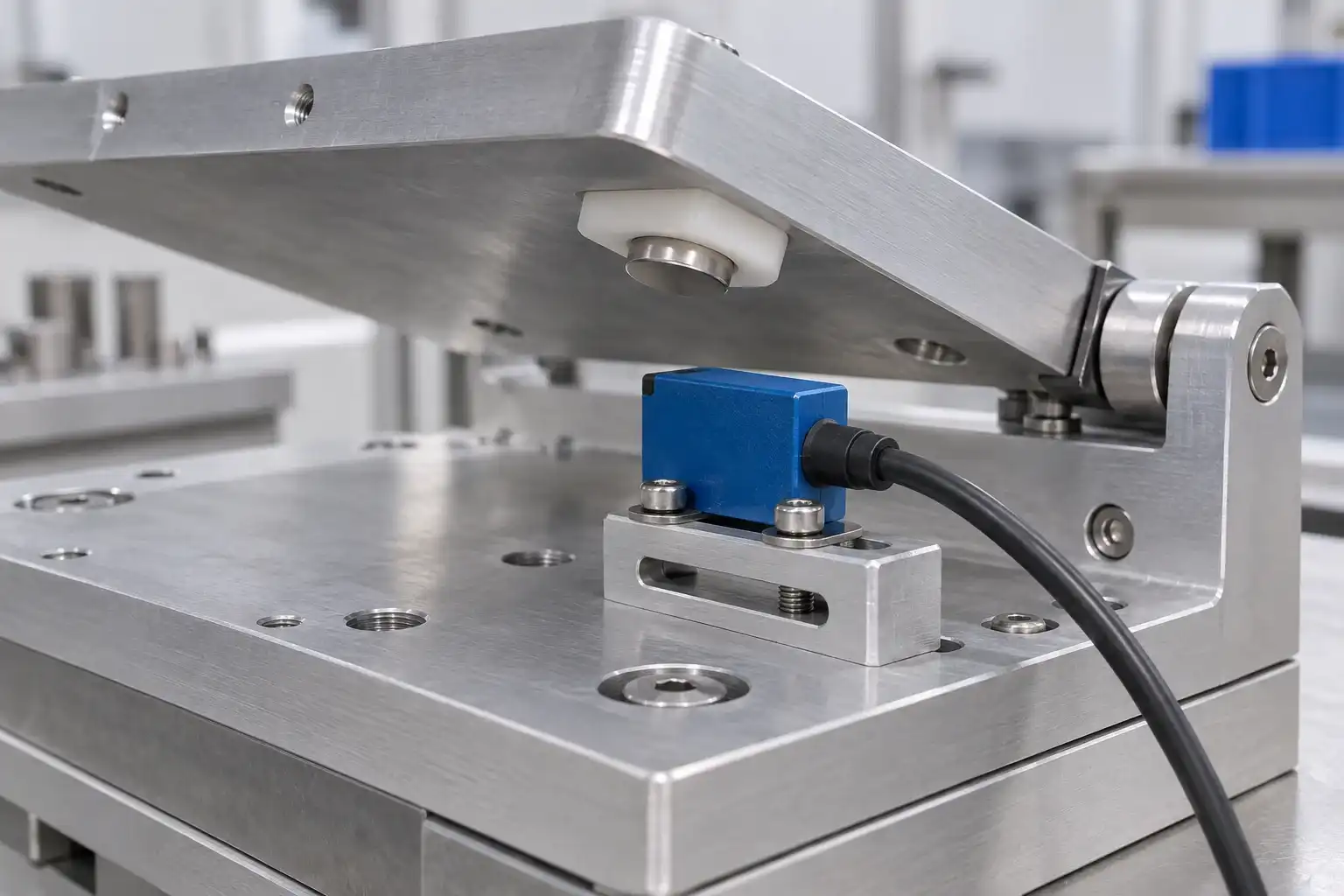
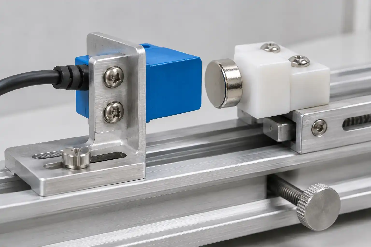
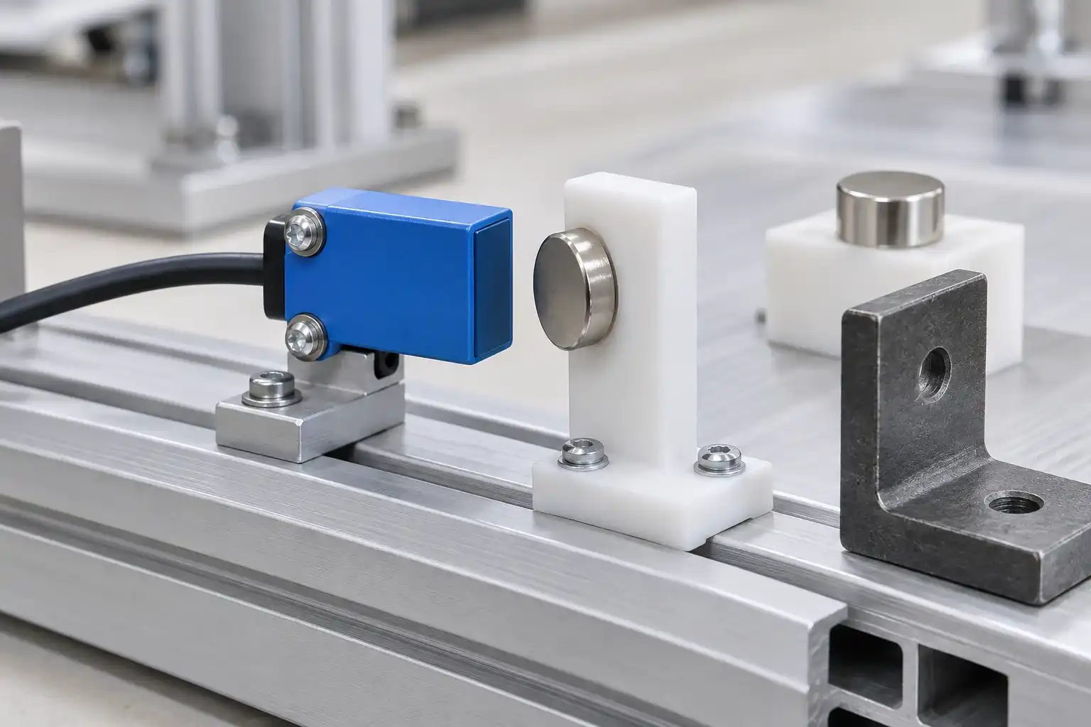
Magnetic switches respond to the magnetic field from a target magnet. Unlike an inductive proximity sensor that detects a metal target, a magnetic switch can confirm the position of a moving component fitted with a suitable magnet, without mechanical contact.
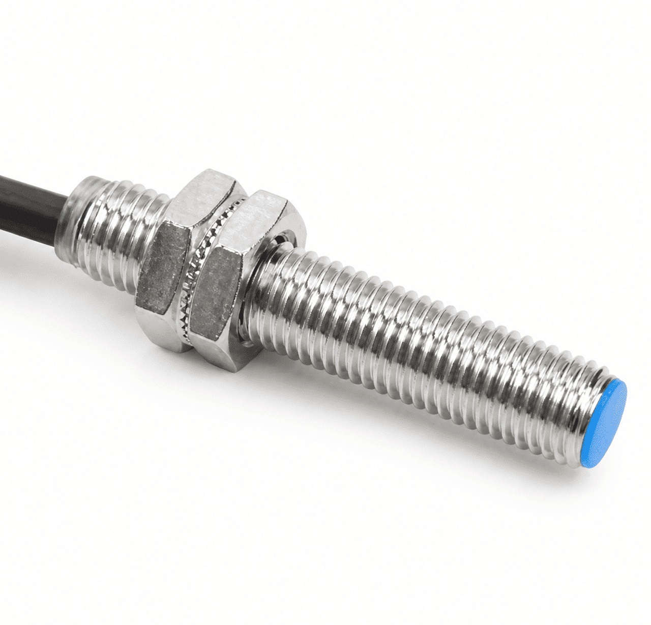
The XSZ Sensor threaded range includes M5, M8, M12 and M18 housings. Select the body for your mounting space, then confirm the target magnet, operating gap, supply voltage, load and wiring for the exact electrical version.
Our Product Range
Match the magnet.
Confirm the operating gap.
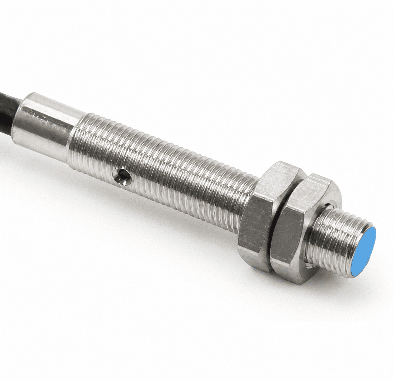
M5 Series
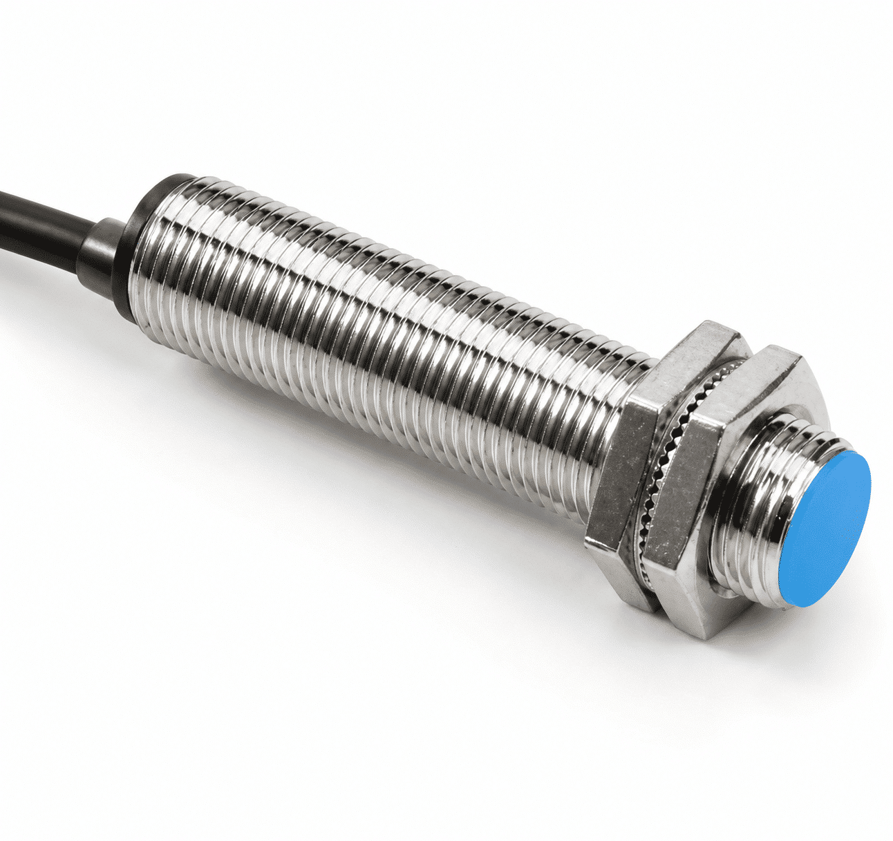
M8 Series
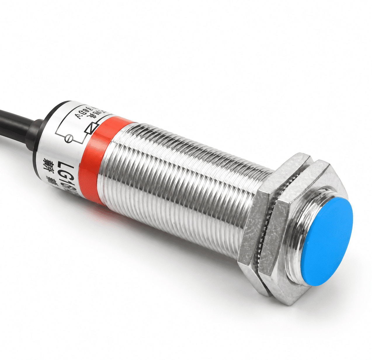
M12 Series
M18 Series
Share your target magnet, operating gap, supply voltage and controller input.
Find the right switch for your application
Match the magnet, mounting position and electrical interface
for reliable position feedback.
Check magnet size, orientation and travel path. Test the operating gap with the magnet used on your machine.
Confirm reed-contact or solid-state sensing. Match the switching behavior and load requirements to your application.
Check the bracket, cylinder groove or clamp. Allow space for position adjustment and cable routing.
Match supply voltage, output logic and load rating. Verify the wiring diagram and compatibility with your controller input.
Compare mounting styles at a glance
Compare common installation formats. Confirm dimensions and electrical options for the selected model.
| Mounting Format | Target | Key Fit Check | Adjustment | Circuit Check | Typical Use |
|---|---|---|---|---|---|
Threaded Housing | External magnet | Thread size and bracket clearance | Set gap with nuts | Voltage, output and load | Fixture position, machine home signal |
Rectangular Housing | External magnet | Mounting holes and active-face direction | Adjust bracket position | Voltage, output and pinout | Compact assemblies, moving carriers |
T-Slot Cylinder Mount | Piston magnet | Groove dimensions and retaining screw | Slide along the groove | Output and PLC input | Cylinder end-position feedback |
C-Slot Cylinder Mount | Piston magnet | Groove profile and insertion clearance | Set position in the slot | Output and PLC input | Compatible compact cylinders and grippers |
Clamp-On Cylinder Mount | Piston magnet | Clamp size and cylinder compatibility | Position clamp on the body | Output, cable and load | Round cylinders with a matching adapter |
Validate performance on your machine
Check turn-on and release positions across repeated cycles with the actual magnet, gap and approach direction.
Check for unwanted signals from nearby magnets, steel fixtures and other sources of magnetic interference.
Confirm the switch stays in position during motion and vibration, with enough clearance for the cable.
Verify that the controller captures every required state change at operating speed with the intended load.
Match the switch to your equipment
Mounting hardware and output availability depend on the selected switch.
Match the sensor position to the magnet's travel path.
Check the model's circuit diagram before connecting.
Check contact ratings and load protection for the intended circuit.
Sinking output, when specified.
Match the controller input.
Sourcing output, when specified.
Verify supply polarity.
Check the output state with the magnet present and absent. Availability varies by model.
Detect a magnetic target without a mechanical lever. From cylinder strokes to moving fixtures, choose a switch that matches the magnet, mounting position and controller input.

Detect the piston magnet at a selected stroke position with a compatible cylinder and switch.

Confirm actuator position in a compatible magnetic gripper; this does not prove part presence.

Use a magnet on the moving carriage to signal a selected reference position.

Monitor a magnet-equipped fixture or cover for process feedback, not safety interlocking.
A magnetic switch responds to a suitable magnetic field, not ordinary metal alone. Check the actual magnet and both switching positions in the installed setup.

Magnet size, field strength and orientation affect switching. Confirm the target and approach direction.

Set the mounting gap and verify turn-on and release points. Allow for movement and vibration.

Nearby magnets and steel fixtures can change the field at the sensor. Test the complete assembly.

Confirm reed or solid-state design, supply, output and load limits. Match the wiring to the controller.
From application review to OEM supply, build a sensing solution around your production line.
Support from
selection to supply.
Review your magnet,
gap and circuit.
Check the selected
configuration.
Validate on your
actual machine.
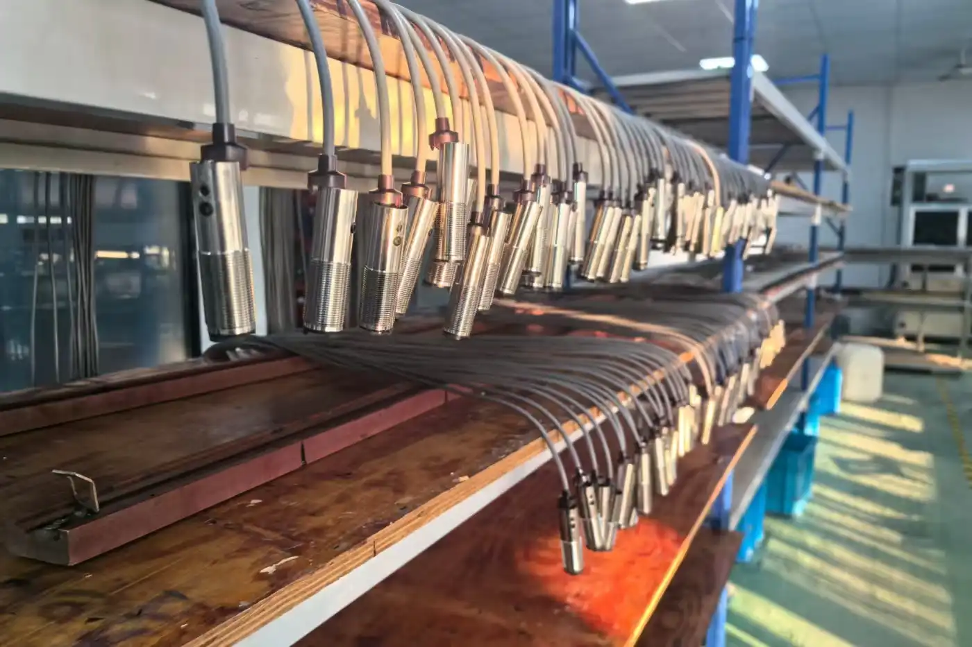
From production to inspection, every step is built for stable quality.







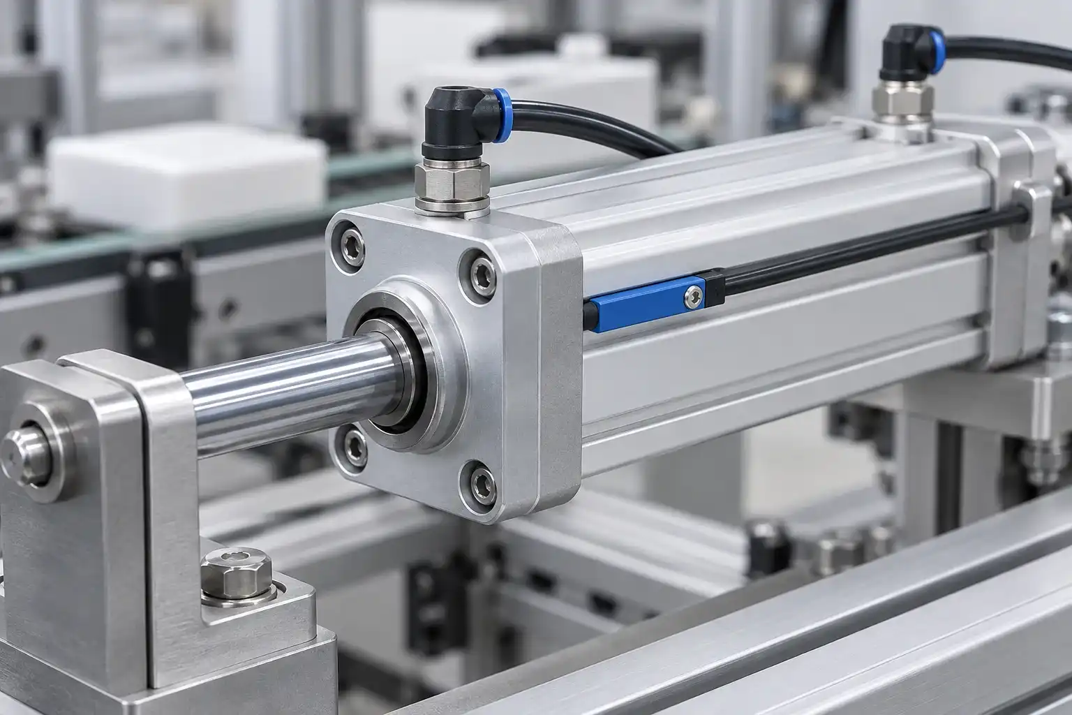
Flexible Solutions for Your Application
Share your target magnet, mounting space and electrical requirements. Our engineering team can review feasible configuration and branding options for your magnetic switch application.
Housing & Mounting
Review housing dimensions, mounting points and available space in your equipment.
Magnet Matching
Check the target magnet, working gap and approach direction as a matched setup.
Cable Length
Discuss cable length and routing for your machine layout.
Connection Type
Review available cable or connector options against your wiring requirements.
Output & Load
Match available switching behavior and electrical ratings to your controller or load.
Label / Branding
Discuss custom labels, logos and part numbers for your OEM project.
Explore More
Practical reading for magnetic switch selection, magnet matching and installation.
Selection Guide
How to Choose a Magnetic Proximity Switch
Review the target magnet, mounting space, working gap and electrical requirements.
Read ArticleTechnology Comparison
Reed vs. Hall-Effect Magnetic Switches
Compare sensing principles and circuit requirements before choosing a switch.
Read ArticleInstallation Guide
Magnet Alignment and Switching Distance
Understand how magnet orientation and approach direction affect the switching point.
Read ArticleCommon Questions
Quick answers to help you select, install and connect a magnetic switch.
It responds to a magnetic field, usually from a target magnet. An ordinary metal part is not a substitute for that magnet; magnetic and inductive proximity switches use different sensing principles.
Do not assume every magnet is compatible. Check the magnet's size, strength and orientation against the chosen sensor, including any polarity requirements, then test the actual combination.
The switching gap depends on the sensor's sensitivity and the magnet's field, size, shape and alignment. Verify it with the actual magnet and installation rather than relying on a generic distance.
Not automatically. A reed switch uses magnetic-field-operated contacts; a Hall-effect switch uses powered electronic sensing. Compare supply, wiring, switching behavior and electrical ratings for the exact models before replacing one with the other.
Follow the model's wiring diagram. Confirm supply voltage, output or contact type, allowable load and controller input compatibility. Do not assume all magnetic switches share the same two-wire or three-wire connection.
Check the working gap, magnet alignment and mounting stability through the complete motion. Review nearby magnetic fields and the electrical connection, then verify switching with the final assembly and operating load.
Let's Build a Smarter Tomorrow
Share your magnet details, working gap, mounting space and controller requirements. Our technical team can help you review a suitable switch and connection.