
Magnet Alignment and Switching Distance: What to Check
For reliable magnetic switch alignment, confirm the actual switch–magnet pair and sensing direction, then record where the output changes as the magnet approaches and moves away along its real path. Recheck those positions after final mounting and at operating speed. A nominal switching distance alone does not establish a reliable installation position.

Before You Start
- Identify the exact switch, its output circuit and whether it is expected to reset when the magnet moves away.
- Use the intended magnet, with its orientation marked so that each check starts from the same arrangement.
- Define the machine positions that require each output state and the permitted travel between them.
- Establish a safe commissioning procedure and a way to observe both the switch output and the receiving input.
Confirm the Switch, Magnet and Required States
Start with the position the machine needs to recognize. A slide at its home position may require one signal state, while the same slide outside that position requires the other. Write down those required states before adjusting the sensor. Otherwise, finding a position that changes the indicator can appear successful even though the signal changes too early, too late or more than once during travel.
The switch and magnet form a detection pair. The magnet's dimensions, magnetization and orientation affect the field at the sensing element; the switch responds according to its own magnetic characteristics. Two magnets that fit the same bracket are not necessarily interchangeable. Likewise, a switching distance specified with one magnet is not automatically valid with another. Check which magnet and approach arrangement the model documentation uses.
Confirm the reset behavior separately from the electrical output logic. A non-latching switch is intended to return to its original state when the magnetic condition falls below its release threshold. A latching device can retain its state and require the documented reset condition. Normally open or normally closed describes contact or output behavior; it does not, by itself, identify a magnetic latch. A signal that remains active after the magnet moves away therefore needs a device-type check before a distance adjustment.
These checks concern ordinary machine position feedback. Follow the equipment's commissioning procedure when changing brackets, wiring or motion settings. Safety interlocks require their specified installation and validation process; this guide does not provide a method for adjusting or bypassing them.
Check Magnet Orientation and the Complete Travel Path
Magnet Polarity and the Sensor’s Sensing Axis
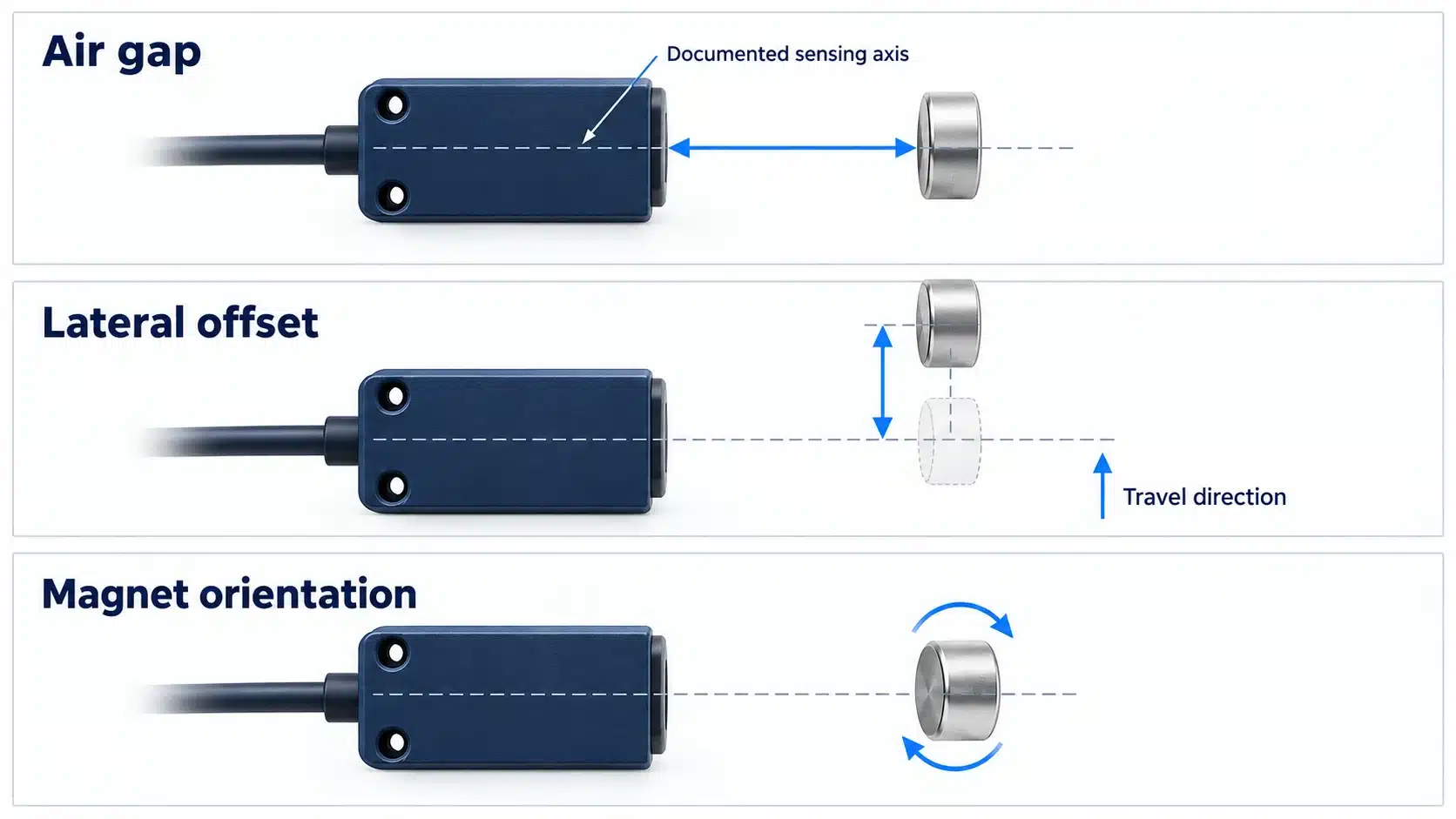
Align the sensing arrangement, not just the outside of the housings. The active element is inside the sensor, and the relevant magnetic field direction may not correspond to the longest side or visible center of its enclosure. Use the model's sensing-face, magnet-orientation or mounting drawing as the starting reference.
For Hall-effect switches, polarity response depends on the device. A unipolar switch responds to its specified polarity, while an omnipolar switch can respond to either polarity. Omnipolar does not mean that every magnet angle works equally well: the required field component must still act along the device's sensitive axis with sufficient strength. Reed-switch arrangements also depend on the magnet's orientation relative to the contacts. Do not transfer a Hall device's polarity rule to an unidentified reed assembly.
If the documentation permits orientation adjustment, mark the magnet and change one variable at a time. Compare positions with the gap and travel path held constant. Rotating the magnet while simultaneously moving the bracket makes it difficult to tell which change produced the result. If the magnet is built into a cylinder or another assembly, use the specified compatible sensor and mounting method rather than treating the internal magnet as freely adjustable.
Air Gap, Lateral Offset and Approach Direction
Keep three measurements distinct. Air gap is the separation between the reference surfaces used for the installation. Lateral offset is displacement across those surfaces. Travel position describes where the magnet is along its route past or toward the sensor. A drawing should show all three, along with the direction of movement. When comparing with a datasheet, use that document's measurement references rather than assuming the outside faces define its stated distance.
These variables change the field reaching the sensing element in different ways. A magnet moving directly toward the sensor does not create the same sequence of magnetic conditions as one sliding past it at a constant gap. In some reed-switch arrangements, a passing magnet can cross more than one region that closes the contacts. Moving the magnet closer can change those regions rather than simply providing a better signal.
Check the whole permitted journey, including the approach, intended detection position and departure. Look for unwanted transitions as well as the required one. Repeat at the permitted lateral and angular extremes of the mechanism. A setup that works only on the nominal centerline may fail when normal guide play moves the magnet onto a different part of the field pattern.
Measure the Switching and Release Positions
Record Both Directions of Travel
Use a fixed machine datum so that recorded positions remain meaningful after adjustment. For an ordinary non-latching arrangement, distinguish the operate position, where the output changes into the detected state, from the release position, where it returns. Record the actual electrical state as well; an “ON” indicator is not a substitute for knowing what the controller should receive.
A practical measurement sequence is:
- Set the documented magnet orientation, gap and offset. Begin at a known position and confirm the initial state.
- Move along the real path at a controlled slow speed using the permitted commissioning method. Record every output transition, not only the first desired one.
- Continue to the end of the permitted path, then reverse and record the transitions again. If the device is latching, follow its documented reset procedure instead of expecting removal alone to reset it.
- Repeat the same route without changing the reference setup. Keep the direction of travel beside each position so that forward and reverse results are not mixed.
- Compare the observed states and transition positions with the machine's required detection window and documented sensor limits.
Do not lock the bracket at the first point that just triggers the output. That point is a boundary observed under one set of conditions. The intended working position needs room for the movement and variation the application actually permits, while the required clear position must reliably produce the opposite state. There is no universal percentage or millimeter allowance that replaces the model's specifications and the machine's positional requirements.
Separate Hysteresis From Repeatability and Installation Tolerance
Hysteresis is the difference between the conditions for operating and releasing the switch. For a non-latching Hall switch, the operate and release thresholds are magnetic-field thresholds. This separation helps prevent repeated toggling when the field fluctuates slightly near a transition. Along a defined movement path, the two thresholds can correspond to different physical positions.
Repeatability asks a different question: how closely does the same transition recur over repeated cycles under the same conditions? To examine it, compare operate positions approached from the same direction. Do the same separately for release positions. Comparing an operate point with a release point primarily shows the switching separation on that path, not cycle-to-cycle repeatability.
Installation tolerance concerns allowed changes in the assembly: gap, offset, angle, bracket position and mechanism play. Replacement units can introduce additional device-to-device variation. A repeatable bench setup does not establish how much of that variation the machine can tolerate. Check the required states at the permitted mechanical extremes and use the manufacturer's guaranteed limits where available.
Magnetic-field thresholds cannot be converted into a general switching distance without the field profile of the particular magnet and geometry. Nor does subtracting unrelated maximum and minimum datasheet limits reveal the measured hysteresis of one installed unit. Keep field specifications, observed travel positions and assembly tolerances as separate records until their relationship has been established for the actual pair.

Recheck the Final Mounting and Operating Environment
Nearby Steel and Other Magnetic Fields
The final bracket and neighboring machine parts belong in the test setup. Ferromagnetic material can redirect magnetic flux, changing the field at the sensor. Nearby magnets add another field contribution. Depending on their positions and directions, these effects can alter an operate point, a release point or the set of transitions during a pass. They do not imply a universal rule that every steel bracket increases or decreases the range.
If the behavior changes between a temporary setup and the machine, compare the surrounding materials and magnetic sources before replacing the switch. Use the final hardware and check the relevant positions of nearby moving assemblies. Follow the model's mounting restrictions; do not assume that a result obtained on a nonmagnetic test support will remain valid when the pair is mounted next to steel.
Bracket Movement, Cable Strain and Temperature
Recheck the positions after tightening. A small bracket movement can change the gap or angle even when the adjustment scale appears unchanged. Cable routing can also load a lightly supported sensor or bracket. Secure the assembly and cable according to their instructions, then repeat the state checks with the final routing in place. Use the specified tightening method and limits rather than a general torque value.
Temperature can change the magnet–sensor relationship as well, so a room-temperature check is only evidence for those conditions. Confirm the permitted temperature ranges of both components and assess the installation at the relevant operating conditions using an approved test method. Do not apply another magnet material's temperature coefficient or another sensor family's drift figure to the installed pair.
The useful acceptance question is whether the required states survive the final assembly and its permitted conditions. If tightening, ordinary cable movement or normal neighboring equipment positions changes the result, resolve that sensitivity before accepting the setup.
Validate the Signal at Operating Speed
Slow movement helps locate switching boundaries; it does not prove that the controller will recognize the signal during production. A magnet can pass through a valid detection region so briefly that the resulting output interval does not satisfy the receiving input's timing requirements. Check the sensor's documented switching behavior alongside the input filtering, capture method and control logic used by the machine.
Observe two points where suitable test access exists: the sensor's electrical output and the state recognized by the programmable logic controller (PLC) or other receiving device. If the electrical output changes correctly but the input does not, investigate the interface and capture settings before moving the magnet again. If the sensor output itself is missing or produces unwanted transitions, return to the pairing, path and mounting checks. The indicator alone does not distinguish these cases.
For electronic outputs, confirm the specified output circuit and its compatibility with the receiver; for contact outputs, confirm the documented circuit and load. The output-type reference can help identify the information to collect, but the exact sensor and input documentation determine the connection. Avoid assuming that all magnetic switches share a supply, wire color or pin assignment.
Run the allowed travel directions and operating conditions through the machine's approved commissioning procedure. Confirm both required states and the transitions the control logic actually uses. Do not compensate for an uncertain detection region by changing a filter or timer until the physical signal and the consequences of that change are understood.
Diagnose Common Alignment Symptoms
Use the symptom to choose a check that separates likely causes. The following table identifies possibilities, not a diagnosis established from appearance alone.
| Observed symptom | Possible mechanism | Distinguishing check | Next step |
|---|---|---|---|
| No output change anywhere on the permitted path | Incompatible magnet, unsuitable orientation or insufficient field; a supply, load or output fault may also be involved | Confirm the electrical setup, then compare the pair and orientation with the model instructions | Correct the identified mismatch before reducing the gap |
| A transition appears in one travel direction but not where expected in the other | Different operate/release positions, a different return path or documented latching behavior | Record the full forward and reverse paths, including initial and final states | Compare each direction with its required machine state and the device's reset behavior |
| The signal remains active after departure | A latch, a magnetic field that has not reached the release condition or a retained controller state | Compare the actual sensor output with the receiver, and check the documented reset condition and surrounding magnets | Resolve the magnetic or control-state cause; do not assume a failed switch |
| One pass produces multiple transitions | More than one magnetic actuation region, mechanical variation or a downstream counting issue | Compare transitions at the sensor output and receiver during a permitted slow pass, then examine the path | Correct the documented mounting or interface issue and repeat the complete travel check |
| Switching positions move after tightening or installation | Gap/angle change, bracket loading or changed magnetic surroundings | Compare the recorded geometry and transition positions before and after final assembly | Stabilize the mounting and retest with final hardware |
| The sensor changes state but the PLC misses it at speed | Output interval or interface behavior does not meet the input's capture requirements | Observe the electrical output and input record under the same operating condition | Check the documented interface and timing limits before changing the alignment |
Record the Setup Before Final Acceptance
Leave enough information for another technician to reproduce the setup and distinguish a changed installation from a changed component. The record should include:
- The switch model, output/reset behavior and magnet identification, dimensions and marked orientation.
- The machine datum, reference surfaces, gap, offset, angle and permitted movement path.
- The required states, measured transition positions in each direction and results from repeated cycles under the recorded conditions.
- The final bracket, nearby magnetic or ferromagnetic parts, cable routing and relevant operating conditions.
- The observed sensor output, receiving-input results, operating speeds checked and the application's acceptance criteria.
Recheck the installation when the magnet, sensor, bracket or relevant operating conditions change. If a required state cannot be maintained within the permitted positions, do not accept a single successful pass as proof of suitability. Review the documented pairing and mounting constraints, and take the position record and installation photographs to the supplier for a compatibility discussion.
For an xsz sensor application, the magnetic-switch category provides a starting point for that discussion. Use the exact model and magnet documentation to agree the installation; a category-level distance is not an acceptance result for the assembled machine.
Technical Sources
- Texas Instruments — Transition Detection Using Hall-Effect Sensors (SLYA055A, revised June 2022): Hall polarity response, sensing arrangements, magnetic thresholds and design variation.
- Texas Instruments — Multi-State Position Selection Using Hall-Effect Sensors (SLVAF61, January 2022): Non-latching Hall-switch operate/release thresholds and hysteresis.
- Standex Detect — How Reed Switches Are Used with a Permanent Magnet: Relative magnet motion, contact behavior and path-dependent actuation regions.
- elobau — Sensors: General Information: Magnet selection and the effects of mounting conditions. Product-specific limits remain specific to the documented sensor family.