Description
E3JK-DS30M1 product overview
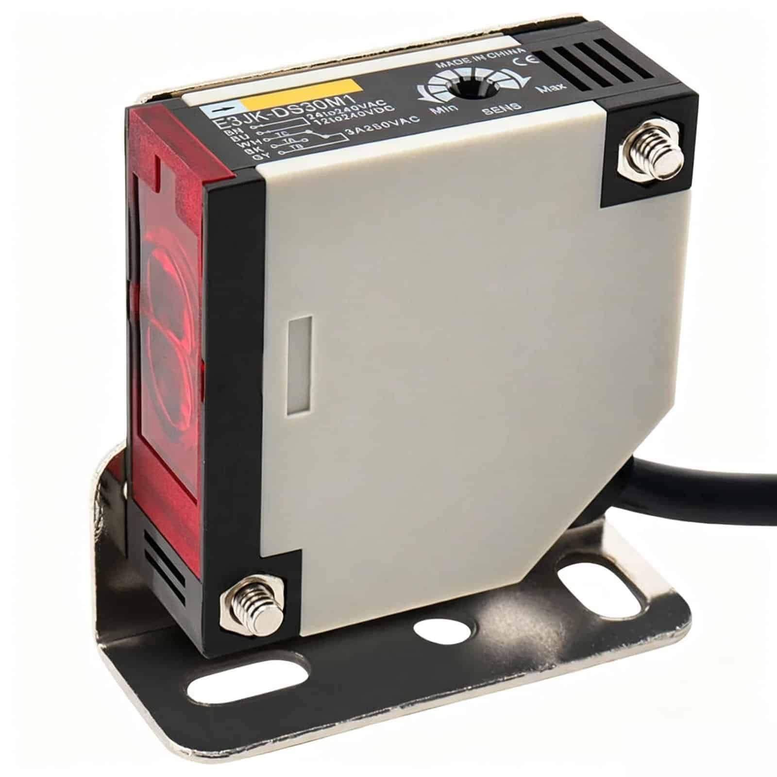
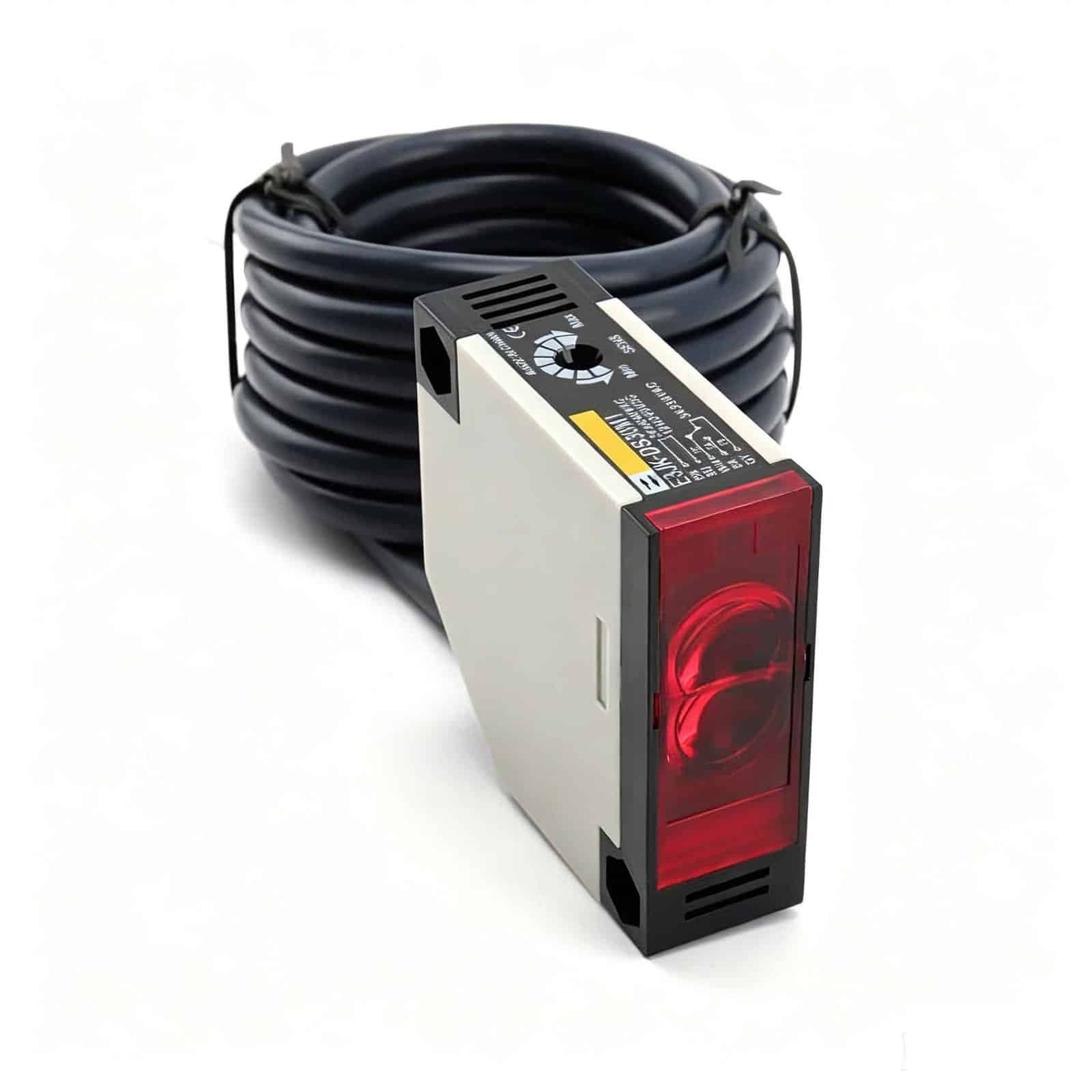
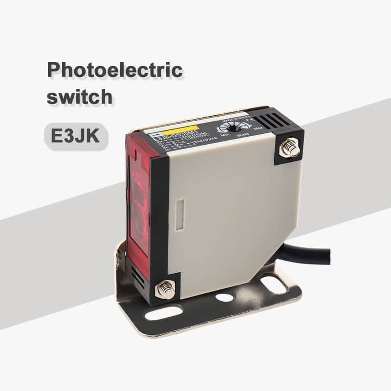
The XSZ E3JK-DS30M1 is a red polymer-housing photoelectric switch with a listed 30 cm sensing distance and five-wire relay output. It provides a non-contact object-presence or position signal for a machine control circuit when the target and electrical interface match the installation.
Check the actual target at the intended gap and confirm the current supply and relay wiring documentation before connecting the unit. The available product information does not establish one optical mode or a verified supply range.
A 30 cm detection point with relay signalling
The 30 cm figure is the listed sensing distance. Photoelectric detection depends on the actual object’s size, colour, surface finish, angle and background, so this figure should be checked under the intended machine conditions rather than treated as identical for every target.
The five-wire relay output offers a contact-based signal option. Confirm the normally open (NO) and normally closed (NC) contact arrangement, relay switching limits and controller input on the exact wiring sheet. The relay rating must be known before a load is connected.
E3JK-DS30M1 specifications
The dimensional and output details below identify this model. Use the current product label, datasheet and drawing to confirm electrical ratings and mounting fit before installation.
Detection and housing
| Model | E3JK-DS30M1 |
|---|---|
| Product type | Photoelectric switch |
| Listed sensing distance | 30 cm; verify with the real target and optical arrangement |
| Housing material / colour | Polymer / red |
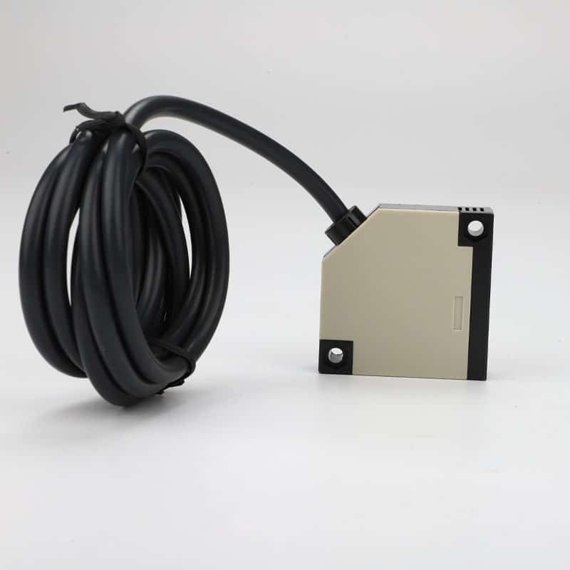
| Body dimensions | 50 × 18 × 50 mm |
| Approximate weight | 80 g |
Output and connection
| Output type | Five-wire relay output |
|---|---|
| Contact logic | Normally open / normally closed configuration; verify actual contact arrangement |
| Supply and relay ratings | Confirm the current product label and wiring specification before connection |
Applications and installation checks
Potential uses include part-arrival or presence checks on conveyors, woodworking equipment and material-handling stations. Whether this model is suitable depends on the optical layout, real target, mounting position and required output response.
Before specifying this switch
- Test the target at the intended distance, including the smallest, darkest or most reflective expected part.
- Confirm the actual optical method and mounting geometry; allow space for aiming and cable routing.
- Verify the supply, five-wire pinout, NO/NC contacts and relay-contact load rating.
- Check the 50 × 18 × 50 mm housing fit and obtain the mounting-hole drawing when precise placement matters.
Frequently asked questions
Is 30 cm guaranteed for every object?
No. It is the listed sensing distance. Confirm the real target’s size, colour, surface and orientation under the intended mounting conditions.
What does the relay output need from the controller?
Check the controller input, the normally open or normally closed contact required, and the approved relay switching rating. Use the current five-wire diagram for connection.
Can the housing fit a compact machine location?
The listed body size is 50 × 18 × 50 mm. Verify the mounting holes, optical face direction and cable clearance on the dimensional drawing.
Which supply should be used?
Use only the voltage and AC/DC type confirmed on the exact product label or approved datasheet. Do not energize the switch based on an unverified range.