

Description
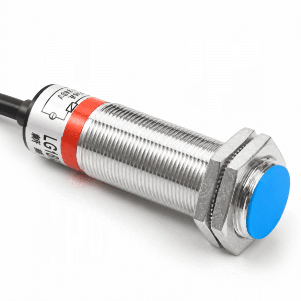
M12 magnetic proximity switch range
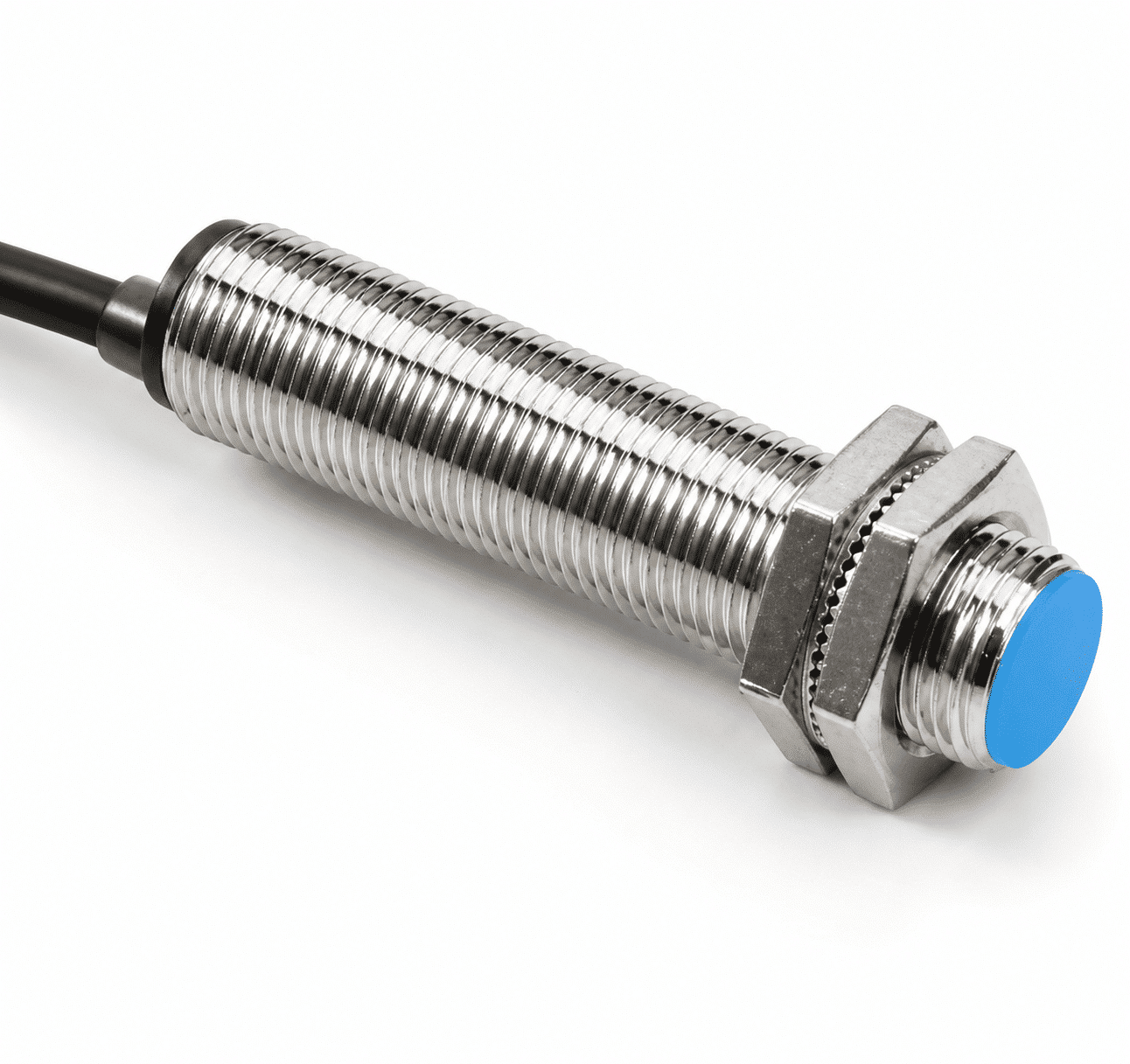
The XSZ M12 magnetic proximity switch range is listed with a shielded body and a 10 mm ±10% sensing distance. The standard target is a Ø8 × 2 mm magnet, and the setting distance is listed as 0–8 mm. The 10 mm figure describes sensing distance, not the physical size of the M12 body.
Four part numbers cover DC and AC two-wire versions with normally open (NO) or normally closed (NC) logic. Choose an exact model code for the controller and power source rather than treating the range as one interchangeable product.
Magnet target and distance planning
The listed 10 mm ±10% sensing distance uses a Ø8 × 2 mm magnet as the standard target reference. The stated 0–8 mm setting distance is a separate installation figure. Check the actual magnet, its orientation, mounting tolerance and movement before relying on a detection point.
The sensing result for a different magnet size, strength or travel path is not established by the reference values alone. Confirm the intended target and switching position under operating conditions.
M12 output and model selection
Each row below is a separate part number. DC two-wire and AC two-wire models require their own approved supply and wiring information; the NO/NC logic cannot be changed by selecting another mode on the same sensor.
| Output family | Logic | Model code |
|---|---|---|
| DC two-wire | NO | LG12A3-10-Z/EX |
| DC two-wire | NC | LG12A3-10-Z/DX |
| AC two-wire | NO | LG12A3-10-J/EZ |
| AC two-wire | NC | LG12A3-10-J/DZ |
Technical specifications
These values describe the M12 range in the available specification. Match electrical ratings and the wiring diagram to the exact model code before installation.
Body and sensing data
| Body format | M12 |
|---|---|
| Shielding type | Shielded |
| Sensing distance | 10 mm ±10%, with the listed standard magnet |
| Setting distance | 0–8 mm |
| Standard target | Ø8 × 2 mm magnet |
| Hysteresis | Less than 10% of sensing distance |
Load and electrical safety
| Continuous load current | 200 mA in the M12 model matrix; confirm for the selected code |
|---|---|
| Insulation resistance | At least 50 MΩ at 500 VDC, between energized parts and housing |
| Withstand voltage | 1,000 VAC at 50/60 Hz for 1 minute, between energized parts and housing |
Environment and materials
| Operating and storage temperature | −30 to +65 °C; no freezing or condensation |
|---|---|
| Operating and storage humidity | 35–95% RH |
| Protection designation | IP67 (IEC) |
| Housing | Nickel-plated brass |
| Sensing face | ABS |
Installation and selection checks
An M12 body can be considered where the mounting layout allows the switch and its target magnet to hold a repeatable relative position. The appropriate magnet orientation, actual switching distance and cable routing should be checked on the intended machine.
Confirm before ordering
- Exact DC or AC two-wire model code and required NO or NC logic.
- Approved supply range, continuous load and wiring diagram for that code.
- Target magnet dimensions, grade and orientation, plus the required switching point.
- Current mounting drawing, cable/connector specification, environmental exposure and response frequency.
Frequently asked questions
Does 10 mm describe the M12 body size?
No. It is the listed sensing distance. M12 describes the body format, while the listed setting distance is 0–8 mm.
Which magnet was used as the standard target?
The listed reference is a Ø8 × 2 mm magnet. Confirm performance with the magnet actually used in the application.
Is M12 one orderable model?
M12 names the body format in this range. Choose a complete part number from the DC/AC two-wire NO/NC table above.
Can the same wiring be used for DC and AC versions?
Do not assume so. Obtain the current supply and wiring diagram for the exact model code before connecting the switch.
Reviews
There are no reviews yet.