

Description
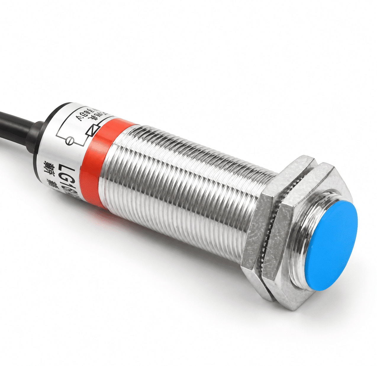
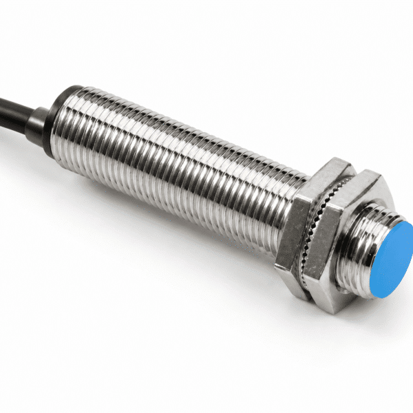
M18 magnetic proximity switch overview
The XSZ M18 series is a shielded magnetic proximity switch range with a listed 10 mm ±10% sensing distance. Its reference target is a Ø8 × 2 mm magnet, with a 0–8 mm setting distance. The actual switching position depends on the magnet and installation conditions, so verify the selected model with the intended target.
The range contains separate DC two-wire and AC two-wire part numbers in normally open (NO) and normally closed (NC) versions. Select the model that matches the supply and controller input; these output modes are not interchangeable settings on one SKU.
| Body format | M18, shielded |
|---|---|
| Sensing distance | 10 mm ±10% |
| Setting distance | 0–8 mm |
| Standard target | Ø8 × 2 mm magnet |
10 mm sensing with a magnet target
The 10 mm sensing-distance figure is tied to the listed Ø8 × 2 mm standard magnet; it is not a guaranteed switching distance for every magnet or mounting arrangement. Position the magnet and switch so the chosen model changes state within the 0–8 mm setting range under actual operating conditions.
For a new installation, check the magnet’s material and geometry, its approach direction, surrounding metalwork and the controller’s required NO or NC behavior. Confirm repeatability and switching response using the final assembly rather than relying on the nominal distance alone.
Technical specifications
Use the mechanical and environmental data together with the exact model’s electrical specification. Supply, load and wiring requirements must match the selected part number.
Mechanical and detection data
| Product type | Magnetic proximity switch |
|---|---|
| Body dimension | M18; confirm full length from the model drawing |
| Construction | Shielded |
| Sensing distance | 10 mm ±10% |
| Setting distance | 0–8 mm |
| Standard detection target | Ø8 × 2 mm magnet |
| Housing | Nickel-plated brass |
| Sensing face | ABS |
Output and electrical selection
| Available output arrangements | DC two-wire or AC two-wire; separate NO and NC models |
|---|---|
| Continuous load current | 200 mA listed in the M18 model matrix; confirm for the selected model |
| Hysteresis | Less than 10% of sensing distance |
Confirm the exact supply range and wiring for the chosen DC or AC model; a DC supply value must not be applied to an AC variant.
Operating environment and safety
| Operating and storage temperature | −30 to +65 °C; no freezing or condensation |
|---|---|
| Operating and storage humidity | 35–95% RH |
| Protection class | IP67 (IEC) |
| Insulation resistance | At least 50 MΩ at DC 500 V, between energized parts and housing |
| Withstand voltage | AC 1000 V, 50/60 Hz for 1 minute, between energized parts and housing |
For applications close to the temperature or switching-distance limits, confirm the influence figures and magnet test conditions for the selected model.
M18 model selection
Choose one of the four listed part numbers by supply category and required switching logic. Each row is a separate model, not a selectable setting of a single switch.
| Output type | Logic | Model |
|---|---|---|
| DC two-wire | NO | LG18A3-10-Z/EX |
| DC two-wire | NC | LG18A3-10-Z/DX |
| AC two-wire | NO | LG18A3-10-J/EZ |
| AC two-wire | NC | LG18A3-10-J/DZ |
Application and installation checks
This series can be evaluated where a magnet is carried by a moving component and a proximity signal is needed. Test the Ø8 × 2 mm reference magnet and the intended mounting geometry on the actual assembly; different magnets or surrounding materials may alter the switching position.
Before finalizing a model
- Select the exact DC/AC two-wire and NO/NC part number, then confirm its supply and controller input.
- Verify magnet size, orientation, travel, and the required switching position within the listed setting range.
- Check the continuous-load rating, switching frequency and model-specific wiring diagram against the selected model’s current specification.
- Confirm full M18 drawing dimensions, cable arrangement, mounting space and operating environment.
Frequently asked questions
Is 10 mm guaranteed with any magnet?
No. The listed sensing distance is referenced to a Ø8 × 2 mm magnet. Confirm the switching position with the magnet and mounting arrangement used in the final machine.
What is the difference between NO and NC versions?
They provide different output logic and have distinct part numbers in the M18 range. Select the logic needed by the controller; do not assume it can be changed on the same switch.
Can the AC and DC models use the same supply?
No common supply range is established. The listed AC and DC versions are separate products; confirm the exact supply specification for the selected model.
What should be confirmed before ordering?
Provide the required model or output logic, supply, controller input, magnet details, switching gap, load, wiring and mounting dimensions.
Reviews
There are no reviews yet.