Description
E3F1 cylindrical photoelectric sensor range
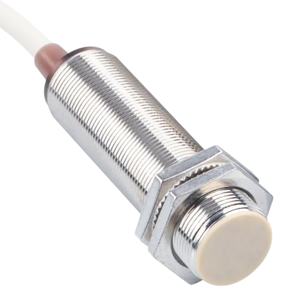
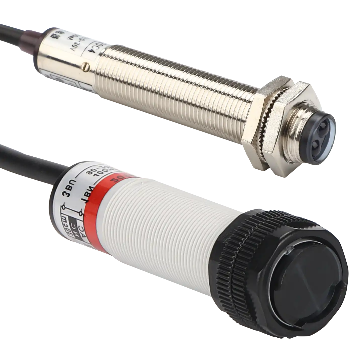
The XSZ E3F1 series brings photoelectric detection into a threaded cylindrical format. The range is presented with diffuse-reflective, retro-reflective and through-beam sensing options, using an infrared LED light source. The housing is listed with metal or heavy-duty plastic options; confirm the construction of the selected model.
Choose an optical mode for the target and installation space, then confirm the exact working distance, output type, mounting dimensions and connection for the selected part number. A cylindrical housing alone does not determine these specifications.
Choose the optical arrangement
The three sensing modes use different layouts. Select the optical path before comparing electrical and mechanical options.
| Sensing mode | Selection consideration |
|---|---|
| Diffuse-reflective | The target returns light toward the sensor. Test the actual material, color, finish, angle and background at the required distance. |
| Retro-reflective | Allow space for a specified reflector and verify alignment, target interruption and the selected model’s working range. |
| Through-beam | Allow mounting on both sides of the detection path for the emitter and receiver; confirm alignment and the distance for the selected pair. |
E3F1 series specifications
The series table below describes listed options and limits. Match them to the current datasheet for the exact optical and electrical model before purchasing or wiring.
Optics and housing
| Housing design | Threaded cylindrical; metal or heavy-duty plastic options |
|---|---|
| Sensing modes | Diffuse-reflective, retro-reflective and through-beam options |
| Light source | Invisible infrared LED |
Power, output and timing
| Power supply notation | 10–30 VDC ±10%; ripple less than 10% peak-to-peak. Confirm the allowable limits for the selected model. |
|---|---|
| Control output | NPN or PNP open-collector options |
| Operating mode | Light-ON / Dark-ON selectable, as listed; verify the switching method for the selected model |
| Maximum load current | 200 mA |
| Response time | 2 ms maximum |
Protection, indication and environment
| Protection circuits | Reverse-polarity, output short-circuit and surge protection |
|---|---|
| Indicators | Red or yellow operation LED; green stability LED |
| Operating temperature | −25 to +55 °C |
| Protection designation | IP67 |
Selection and installation checks
Match the optical mode to the object and the machine layout. For reflected-light modes, test the actual target and nearby background. For through-beam or retro-reflective arrangements, verify the opposing component’s position and alignment. The working distance is model-dependent and is not established by the shared series table.
Confirm for the selected model
- Exact model code, optical mode, working distance and required emitter/receiver or reflector.
- Body thread, length and material, bracket fit, cable or connector, and optical alignment.
- NPN or PNP output, supply limits, Light-ON/Dark-ON behavior and current wiring diagram.
- Target color, finish and size, production speed, background, contamination and operating temperature.
Frequently asked questions
Does the cylindrical housing define the sensing mode?
No. E3F1 is presented with diffuse-reflective, retro-reflective and through-beam options. Select the mode by optical layout and the actual detection task.
What sensing distance does the E3F1 series provide?
The shared specification does not give one distance for the entire series. Confirm the working range for the exact optical model and test it with the intended target.
Is NPN or PNP available?
The series specification lists NPN and PNP open-collector output options. Confirm which output belongs to the selected part number and match it to the controller input.
Can one wiring diagram be used for all E3F1 options?
Do not assume so. Obtain the current wiring diagram and connection details for the exact model, especially when comparing NPN and PNP versions.