
Reed vs. Hall-Effect Magnetic Switches: Key Differences
A reed switch uses a magnetic field to move electrical contacts. A Hall-effect switch uses a powered electronic circuit to detect the field and change its output. Reed sensing can suit a passive contact interface; Hall sensing can suit electronic control without mechanical contact bounce. The better choice depends on the load, magnet behavior and event timing—not simply whether the device is mechanical or solid-state.
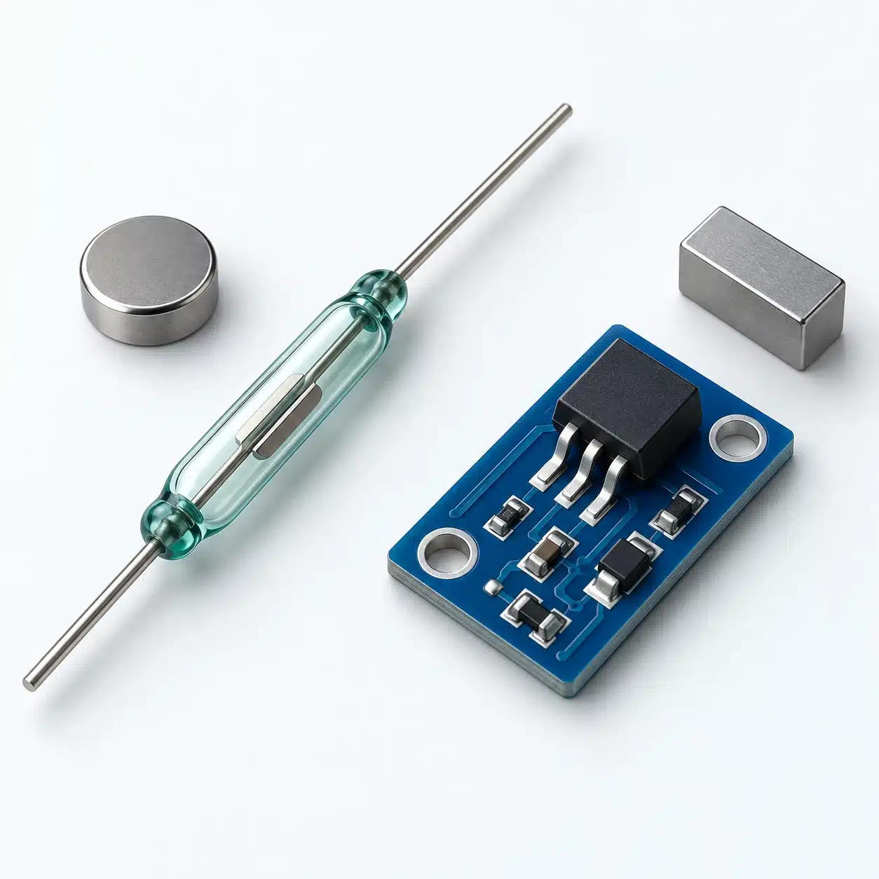
Quick Comparison: Reed vs. Hall-Effect Magnetic Switches
Compare the complete sensing arrangement, including the magnet and receiving input. The characteristics of a bare component do not automatically describe a finished industrial sensor.
| Selection factor | Reed switch | Hall-effect switch | What to verify |
|---|---|---|---|
| Switching mechanism | A magnetic field moves contacts | A Hall element and electronic circuit control an output | Whether the product exposes contacts or an electronic interface |
| Sensing power | A bare reed contact needs no separate sensing supply | The sensing circuit requires power | Complete sensor wiring, supply and circuit consumption |
| Electrical interface | Contact form and load ratings govern use | Output architecture and electrical ratings govern use | Input compatibility, voltage, current and load behavior |
| Magnet response | Depends on contact construction and the magnetic arrangement | May be unipolar, omnipolar or latching | Required polarity, sensing axis and release behavior |
| Dynamic operation | Operate/release time and contact bounce matter | Response delay and any sampling interval matter | Shortest required event and receiving-input timing |
| Service life | Electrical switching conditions affect contact wear | No mechanical contacts to wear, but electrical and thermal limits remain | Actual load, operating conditions and qualified life data |
A useful comparison therefore starts with the signal your machine needs. Decide whether it must report a maintained position, capture each passing magnet, or retain a state until a deliberate reset. Then assess the electrical connection and magnetic arrangement that can produce that signal.
How Reed and Hall-Effect Switches Work
Reed Switches: A Magnetic Field Moves Electrical Contacts
A conventional reed switch contains flexible ferromagnetic contacts sealed inside a capsule. In a common normally open design, a suitable magnetic field attracts the contact ends together and completes the circuit. As the field decreases sufficiently, the contacts separate again. Normally closed and changeover contact forms also exist.
The moving target does not have to touch the switch, but the switch still has moving contacts internally. This explains an important distinction: magnetic actuation can be contactless at the machine interface while the electrical switching remains mechanical.
The contact state depends on the field acting on the reeds, not merely on whether a magnet is nearby. Mounting the magnet at a different angle or passing it along a different path can change where the contact operates and releases. For position feedback, the useful question is whether those transition positions correspond to the machine positions you need to distinguish.
Hall-Effect Switches: A Powered Circuit Detects a Magnetic Field
A Hall element is biased with current. A magnetic field acting along its sensitive direction produces a transverse voltage; circuitry processes that signal and compares it with switching thresholds. A digital Hall switch then changes an electrical output without moving contacts.
The sensing principle and the output function are separate. An analog Hall sensor reports a varying signal, while a digital switch reports a state determined by thresholds. This comparison concerns switching devices. A Hall-based product may also include latching behavior, so “Hall-effect” alone does not tell you what happens when the magnet leaves.
In practical terms, the electronics make output behavior a selection variable. Confirm the device's switching characteristic and interface before deciding how to connect it or interpret its signal.

Compare Power Requirements and Electrical Outputs
Bare Reed Contacts vs. Complete Sensor Assemblies
A bare reed switch does not need a supply to energize its sensing mechanism. The magnetic field moves the contacts, and those contacts open or close an external circuit. That does not make the entire installation power-free: the load, input circuit or monitoring electronics can still draw current.
A finished sensor may contain more than the sensing element. If its circuit includes an indicator or protection components, treat the published circuit diagram as the authority for connection requirements. Do not infer a potential-free contact, polarity independence or a particular voltage rating solely from the word “reed” or the number of wires.
A Hall sensing circuit needs electrical power. In a battery-powered design, compare the consumption of the complete arrangement, including how the output is monitored. A low-power sensing element is only one part of that calculation. In an industrial installation, the immediate question is usually whether the available supply and input circuit match the finished sensor's ratings.
Matching the Switch Output to the Load or Controller
A contact provides a conductive path when closed; an electronic output has a defined circuit relationship to its supply and reference. They should not be treated as interchangeable terminals.
For example, an open-drain Hall output pulls the signal toward its reference when active and needs an appropriate pull-up or receiving circuit to establish the other state. A push-pull output actively drives both states. Industrial sensor assemblies may expose other interfaces, including specified sinking or sourcing outputs. A small Hall IC's output is not automatically compatible with an industrial PLC input.
Before substitution, separate three questions:
- What makes the sensor change state: field magnitude, polarity and switching logic?
- What electrical signal does it produce: a contact, sinking output, sourcing output or another documented interface?
- What does the receiving input need to recognize each state reliably?
Check input thresholds, output ratings, off-state leakage where applicable and the voltage available in the active state. For a reed contact, distinguish the current it can carry while closed from the current it can safely switch. A rating for one condition does not authorize the other.
NO/NC describes the specified switching state or logic; it does not identify NPN/PNP output compatibility or the required magnetic pole. These are separate selection fields. A replacement that reacts to the magnet can still be unsuitable electrically.
Check Magnetic Polarity, Alignment and Reset Behavior
Unipolar, Omnipolar and Latching Hall Devices
A unipolar Hall switch responds to one specified magnetic polarity. An omnipolar switch can respond to either polarity, subject to its thresholds and sensing direction. Omnipolar does not mean that magnet orientation and placement no longer matter.
A conventional bipolar Hall latch uses one field polarity to enter a state and the opposite polarity to release it. Simply moving the magnet away may leave the output latched. A non-latching position switch and a latch can therefore produce different results during the same mechanical movement.
The operate point, often written as BOP, is the magnetic threshold for changing into the active state. The release point, BRP, defines the return transition. Their separation provides hysteresis: operation and release do not occur at the same threshold. This helps separate the two transitions, but it does not guarantee correct behavior along every magnet path. The output-versus-field characteristic shows the required sequence more clearly than a product label alone.
For a mechanism that must report “magnet present” and “magnet absent,” confirm that the selected device releases under the field conditions reached at the absent position. For a latch, confirm that the movement provides the required opposite-polarity reset. Check the documented power-up behavior as a separate requirement; do not assume that a restart establishes the desired state.
Reed technology is not automatically non-latching either: specially biased latching reed arrangements exist. Use the selected product's characteristic rather than treating “reed” and “Hall” as complete logic descriptions.
Why the Magnet and Mounting Determine the Switching Position
Switching distance belongs to a sensor-and-magnet arrangement. Magnet characteristics, orientation, the sensitive axis and nearby ferrous material influence the field reaching the sensor. A distance quoted with one actuator is not a universal distance for any magnet of similar appearance.
This has a practical consequence for tolerances. A nominal assembly may switch correctly while a shifted magnet or a different mounting gap moves the transition outside the required position window. Likewise, a magnet can activate the sensor at the intended endpoint yet fail to move far enough away to produce a dependable release.
Evaluate the complete approach and withdrawal path with the final bracket and nearby metal in place. Record both transition positions and check permitted sideways movement and angular variation. Moving the sensor closer is not a complete solution if it improves activation while preventing release at the other endpoint. The installation needs margin for both states.
Compare Switching Speed, Contact Bounce and Service Life
Contact Bounce and Input Filtering
When reed contacts close, they can briefly make and break contact before settling. A receiving circuit that responds to every edge may interpret that single physical movement as several events. For a maintained-position signal, the concern may instead be a short period of unstable state reporting.
Debouncing or input filtering can reject unwanted transitions, but the filter must still pass the shortest valid event. Increasing a filter time until false transitions disappear is not enough: check that legitimate events remain detectable at operating speed. The appropriate setting depends on the contact behavior, signal duration and receiving input.
A Hall switch removes mechanical contact bounce. It does not eliminate every cause of repeated transitions. If the magnetic movement crosses the switching and release thresholds repeatedly, the output can change accordingly. Distinguish contact bounce from real field transitions before deciding that a technology change will solve a counting problem.
Hall Sampling Rate and Real Operating Speed
Solid-state does not mean that every Hall switch continuously observes the field with negligible delay. Some low-power devices sample periodically to reduce consumption. A short magnetic event can occur between observations, so nominal machine cycle frequency alone is not enough to establish detection capability. The DRV5032 family documentation provides a concrete example of selectable sampling-rate variants; those options are not specifications for other Hall sensors.
Start with the shortest interval during which the actual field satisfies the selected sensor's operate condition. Then check the documented detection delay, sampling behavior and release timing. Finally, confirm that the resulting electrical state lasts long enough for the receiving input and its configured filter to recognize it.
These are separate parts of the same signal path. A sensor can change state correctly while the controller misses the resulting pulse. Conversely, a fast input cannot recover an event that the sensor never detected. Verify the signal at the sensor output and the corresponding controller event under the same motion conditions.
Electrical Load and Service-Life Expectations
Reed contact life depends on what the contacts switch. Opening an inductive load can create a voltage transient and arcing, while capacitive inrush can stress the contacts on closure. A low-current signal circuit and a directly switched coil are different duties even when they use the same reed element.
Assess the load type, switching voltage, current and any protection circuit together. Contact protection must suit the actual circuit; a suppression arrangement for a DC load cannot simply be assumed suitable for AC operation. Where an interface stage is needed, select and verify it as part of the system rather than applying a generic component value.
Hall devices have no mechanical contacts to wear, but their circuitry still has voltage, current and temperature limits. Removing contact wear does not remove output overload, supply faults or unsuitable operating conditions.
Compare qualified life information under the intended duty. Do not compare a reed's electrical endurance under a stated load with an unrestricted claim of solid-state life. The useful purchasing question is what evidence supports the selected assembly in the proposed application, not which technology has the larger headline number.
When Each Technology Is a Better Starting Point
Start with a reed option when a passive contact is genuinely useful. This can fit a position-monitoring circuit designed to read contact closure, provided the contact ratings, magnetic path and dynamic behavior meet the requirement. The benefit is a straightforward sensing element without a separate sensing supply. The trade-off is that contact loading and bounce still need attention.
Start with a Hall option when electronic switching addresses a real requirement. Repeated motion detection can benefit from avoiding mechanical contact bounce, provided the selected device observes the shortest event and its output matches the receiver. Choose the magnetic logic deliberately: a non-latching switch suits a different state-reporting task from a latch that requires polarity reversal.
For an existing installation, start with compatibility rather than a preferred technology. Establish what the original sensor reports, how the input is wired, which magnet operates it and when it must release. A change may require a different interface or magnet arrangement even if the replacement fits the same mounting space.
Neither technology name by itself establishes suitability for a safety interlock. Safety-related functions require an appropriately specified system and device documentation; this comparison does not establish that approval.
Validate the Sensor and Magnet Before Ordering
Test Both Switching States in the Final Installation
Use a controlled test arrangement with the intended electrical interface. Keep machine motion safely controlled, and follow the equipment's isolation procedure before changing wiring or mounting.
- Identify the exact sensor and magnet. Retain their part references, circuit diagrams, supply requirements, switching characteristic and mounting orientation.
- Establish the required state at each machine position. Include what must happen on approach, withdrawal and any required reset, rather than testing activation alone.
- Check the slow movement first. Map operation and release over the complete permitted path, including the extremes of gap, sideways movement and angle.
- Repeat under the intended operating conditions. Include the shortest events, final surrounding metal and the temperature or supply variations relevant to the specification. A nominal bench check is not evidence for untested conditions.
- Compare the electrical output with the receiving input's record. Look for extra transitions, missed events and delayed release. Check filtering only after identifying where the discrepancy occurs.
- Record the setup and acceptance result. State which conditions were tested, which remain untested and whether the observed switching positions and event capture satisfy the machine requirement.
For sampled or latching devices, include the documented start-up and reset behavior in the test plan. A repeatable normal cycle does not by itself establish what happens after power returns or the magnet stops in an intermediate position.
Information to Confirm With the Supplier
Provide the sensor location and available mounting space, magnet specification and orientation, complete movement path, required state sequence, operating speed and shortest event duration. Add the available supply, load or controller-input details, expected environment and acceptance criteria.
Ask for the exact output circuit, operate/release characteristic, timing limits and applicable electrical-load ratings. Where life is important, request evidence under a comparable duty rather than a general technology claim. Confirm which sensor-and-magnet combination the supplied data covers.
The final choice should leave you with a documented interface and a workable validation plan. That is a stronger basis for ordering than a sensor that merely switches once when a magnet is held nearby.
Technical Sources
- Texas Instruments — Replacing Reed and Magnetoresistive Switches With Cost-Effective, Low-Power Hall-Effect Switches, SLYA090B, revised August 2025. Sensing principles and magnetic arrangement considerations.
- Littelfuse — Position and Movement Sensor Solutions: Technical Information, 2023. Output interfaces, magnetic installation factors and device limitations.
- Texas Instruments — DRV5032 product documentation. Model-family example of sampling and output variants.
- Texas Instruments — Designing with Hall-Effect Switches & Latches. Operate/release thresholds and switch-versus-latch behavior.
- Littelfuse — Reed Switch Terms, 2016. Contact forms, bounce and electrical-rating terminology.
- Littelfuse — Inductive Load Arc Suppression, 2016. Load-related contact stress and protection trade-offs.