
Photoelectric Sensor Alignment and Troubleshooting Checklist
To troubleshoot a photoelectric sensor, first identify its sensing method and the output state expected with the target present and absent. Check whether the sensor itself changes state before moving its bracket or changing sensitivity. If it does not, examine the light path, target and environment. If it does, trace the electrical output to the receiving controller. Finally, repeat the check with actual parts at operating speed; a stationary pass does not prove reliable production detection.
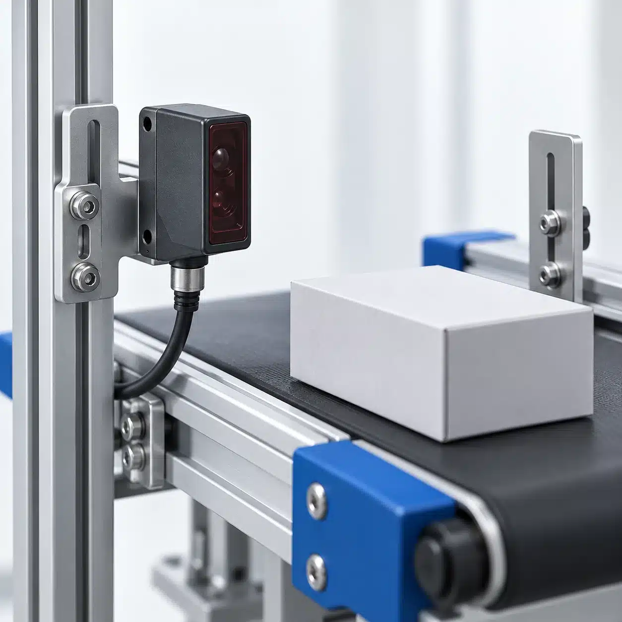
Quick Diagnosis: Find the Failing Part of the Detection Chain
Treat the installation as three connected parts: the optical path establishes what light reaches the receiver; the sensor interprets that light and changes its output; the machine input must then recognize that change. A fault in any one part can look like “poor alignment” from the operator's position. Testing them in order avoids compensating for a wiring or input problem by turning an optical adjustment.
Before powered testing, use the machine's authorized procedure for safe access and motion. Isolate hazardous energy before mechanical or wiring work, and restore power only under the appropriate commissioning controls. An ordinary workpiece-detection photoelectric sensor is not a personnel-protection device.
Use this short triage sequence, recording the result at each step:
- Read the exact model label and manual. Identify through-beam, retro-reflective, diffuse or distance-settable/background-suppression operation; note the specified indicator meanings and output type.
- With the target absent and then present, observe the sensor's indication without changing its position. Record both states. An LED may indicate received light, operating stability or output status, depending on the model.
- If the indicated state does not change as expected, inspect the correct optical path and the real target. Check for obstruction, dirty optical faces, loose mounting, competing light and an unsuitable target/background condition.
- If the sensor indicates the expected change but the machine does not, verify the documented supply and output circuit, then check the receiving input's observed state. Do not infer the wire assignment or switching logic from a similar-looking sensor.
- After correction, test the full target travel, worst-case samples and normal machine speed. Record both successful detection and a reliable return to the target-absent state.
Confirm the Expected Clear-Beam and Target-Present States
The words “light” and “dark” describe switching logic, not a universal rule that an illuminated LED means “object detected.” A through-beam or retro-reflective receiver normally has a return path when the target is absent; an opaque target interrupts it. A diffuse sensor normally depends on light returned by the target. The same physical event can therefore produce different light-received states. A light-on/dark-on or NO/NC setting can also invert the output the controller sees.
Draw a two-row test record: target absent and target present. For each row, note the actual light/reception indication, output indication where provided, measured or monitored output state, and controller input state. Use the exact model's instructions to interpret each indication. If the states were never defined, a technician may “correct” an installation that was actually switching as configured.
Align the Optical Path for the Sensing Method
Alignment means arranging the actual emitter, receiver, reflector or target so the intended optical change is distinguishable throughout permitted movement. The method depends on where the return light comes from. Start with the correct geometry, then use the model's stability or received-light indication if available; a single edge-of-range switching point is a weak acceptance criterion. Do not copy another model's sensitivity or teach procedure.
Through-Beam: Center the Emitter and Receiver
With separate emitter and receiver units, make sure the unobstructed beam reaches the receiver over the complete installation distance. Inspect that both optical faces point toward each other and that the intended target crosses the beam, rather than passing above, below or beside it. If the mounting permits adjustment, find the region where reception is stable and set the pair near its center according to the model's instructions. Avoid accepting the first position at which an LED turns on: slight vibration or a later bracket movement may push that edge position out of range.
Then interrupt the beam with the smallest relevant target feature at the extremes of permitted travel. Confirm a distinct target-present state and a return to the clear-beam state between parts. If the pair works only when held by hand, inspect the support and fasteners before changing sensitivity. Vibration or shock can shift an optical axis; the repair is to restore a stable light path, not merely to obtain one successful stationary interruption.
Retro-Reflective: Check the Sensor and Reflector
Here the sensor sends light toward an opposing reflector and receives the returned light. Check the reflector's position, condition and suitability for the exact sensor. The target should break the intended return path at the detection point. Test once with the path clear and again with the actual target in place; verify both sensor and output states. A sensor aimed at nearby reflective metal may appear aligned while receiving a return that bypasses the intended reflector.
Inspect both optical surfaces and the mounting of both components. Dirt, damage or a reflector that moves relative to the sensor reduces the available signal margin. Shiny or transparent targets can behave differently from an opaque test card, so a card alone cannot qualify the application. Use the model-specific reflector and target guidance rather than assuming that every reflective object works interchangeably.
Diffuse and Background-Suppression: Check the Target and Background
A diffuse sensor receives light from the target itself. Place representative targets at their nearest and farthest normal positions, including the darkest, glossiest or most steeply tilted surfaces expected in use. Check that target-present and target-absent states remain distinct. If a stationary bright sample switches but a darker production part does not, moving the sensor slightly may mask the underlying loss of return light. Compare the target and background under the actual installation lighting instead.
For a background-suppression or distance-settable model, determine its specified sensing zone and adjustment method before changing a cutoff or teach value. The goal is to distinguish the required target positions from the background positions, not just to make one target switch. Test both the farthest target and the nearest background with the actual surfaces. A cutoff established with a substitute material or at one point on a sloped target may not separate all operating conditions. Refer to the exact manual; no generic distance setting or XSZ model figure is implied here. For a family-level overview, see XSZ's background-suppression sensor category.

Troubleshoot Missed Detection and False Triggers
The symptom tells you which comparison will be useful, but it rarely identifies one cause by itself. Change one test condition at a time and observe the sensor state before altering settings. The table is a field guide to distinguish paths, not a substitute for the model manual.
| Observed symptom | Discriminating check | What the result suggests | Next action |
|---|---|---|---|
| Target passes with no sensor-state change | Hold a representative target in the intended path; compare the received-light indication with and without it | The target may miss the beam, return too little light or fail the taught distance condition | Check optical geometry, target/background and the model's sensing setup |
| State changes only when the bracket is touched | Observe reception while the support is gently checked under a safe stopped condition | The optical margin or mechanical support may be unstable | Correct the mount, then realign and retest |
| Switching varies with light, dust or nearby machines | Repeat with the same target while recording lighting, cleanliness and adjacent-sensor operation | External illumination, contamination or mutual interference may be involved | Inspect optical faces and installation conditions; use the documented countermeasure for the model |
| Sensor state changes, but the machine input does not | Compare the documented output state with the receiving input indication | The fault may be electrical, logical or in input capture rather than optical | Verify supply, circuit type, connection and controller configuration |
No Sensor State Change When the Target Arrives
First establish whether the target actually changes the light received by the sensor. For a beam-interruption system, check that the target's required feature crosses enough of the effective beam at every permitted position. A large housing can be correctly mounted while its optical axis is misplaced relative to a narrow feature. For diffuse sensing, examine the actual surface and background. A target that reflects little light, or one whose position varies, may never create a dependable difference at the receiver.
If a known opaque test object changes the state but the production part does not, the sensor is responding to a different optical condition than the process supplies. Do not declare the device failed yet. Record target size, material, surface, orientation and travel; then test the model's documented adjustment range or consider whether a different optical arrangement is needed. If neither the test object nor the real part changes the indicated state, inspect power and the basic light path before evaluating the target in detail.
Unstable Switching After Initial Alignment
An installation can pass once and then chatter or miss intermittently because it operates close to the switching boundary. Look for a pattern. Failure after the machine starts moving points toward bracket deflection, vibration or changing target position. Failure after dirt accumulates points toward declining optical return. Failure when a neighboring emitter or strong ambient light is present suggests optical interference. A failure that follows cable movement may require an electrical inspection instead.
Use a repeatable contrast test: hold target type and position constant while changing only the suspected condition, under safe test arrangements. Clean and inspect optical surfaces as directed by the model manual; do not use a solvent or cleaning method simply because it worked on a different device. Where multiple photoelectric sensors face each other, compare behavior with adjacent emitters in their normal states. Do not prescribe a universal separation distance or interference setting; these depend on the model and layout.
Separate an Optical Fault from an Electrical or Controller Fault
The optical receiver, the electronic output and the PLC or controller input are related but are not the same observation point. A stable received-light indication does not prove the output is wired or configured as intended. Likewise, an output that switches at the sensor does not prove a short pulse is captured by the machine input. This distinction prevents repeated mechanical adjustment of a sensor whose light path is already adequate.
Check Power, Output Type, and Switching Logic
Use the exact order code and wiring diagram to identify the supply range, output circuit, connector pins and light-on/dark-on or NO/NC selection. With qualified electrical access, check the supply at the sensor under the machine's operating condition, then the output with a compatible load or monitored input. A no-load meter reading or LED alone may not reproduce the installed circuit. Follow the equipment's electrical safety procedure; never swap conductors by trial and error or apply an assumed voltage.
If the sensor indicates a state change but the output does not follow the documented function, investigate the sensor's configuration, connection, load and device condition. If the output follows correctly, move the diagnostic boundary downstream. XSZ's output-type guide can orient a buyer to output categories, but the specific sensor and controller manuals determine the actual connection.
Check What the Controller Actually Receives
Observe the receiving input while repeating the same target/no-target test. Check that the input type and common/reference connection match the sensor's specified output, and that the program interprets the selected switching logic correctly. A mismatch can make a sound optical setup appear permanently on or off. If the input changes during a slow test but production counts still miss, compare the output pulse and input capture conditions at real speed. The sensor's response specification, any output timing function, input filter and scan or event-capture method belong in that review; none can be inferred from a visual indicator alone.
Record which boundary fails: received-light indication, sensor output, input terminal/diagnostic state, or application count. This observation narrows the next repair. Avoid changing a controller filter or bypassing a machine safeguard merely to hide an unresolved optical or wiring problem.

Verify Alignment Under Real Operating Conditions
After a correction, confirm that the detection point has enough margin for the process rather than proving only that one object can trip it. Use the actual range of parts, locations and environmental conditions. The acceptance test should show both reliable detection and reliable clearing; a sensor that remains active between parts can be as disruptive as one that misses a part.
Test Target Variation, Contamination, and Mounting Stability
Select representative worst-case samples: smallest required feature, darkest or most reflective surface, greatest permitted tilt, and near/far positions if those conditions exist in the process. Pass each through the complete path. Check the position of supports and fasteners after final tightening, and inspect cable movement if the sensor or machine axis travels. Test with normal adjacent lighting and nearby sensors operating. If contamination is expected, define an inspection/cleaning interval from the site conditions and the device instructions rather than assuming the clean-room result will persist.
If a particular sample fails, write down the failing condition instead of simply increasing sensitivity. That adjustment may recover a dark target but also make a background, reflector bypass or stray light appear valid. The desired result is separation between all intended target states and all intended no-target states within the model's permitted settings.
Confirm the Signal at Production Speed
Run an authorized test using actual parts at the normal operating speed and spacing. Observe the sensor output and controller input or count together if the machine provides suitable diagnostics. Include the shortest expected gap between successive targets, because the output must return to the inactive state when the process needs two distinct events. A slow hand test cannot show whether the complete detection chain captures that gap.
Do not turn a stated switching frequency into a guaranteed line rate. The valid rate depends on the exact target geometry, transit time, sensor response in both directions, output configuration and controller input timing. If the sensor changes state but the controller misses events, document the pulse behavior and input settings for the controls engineer. If the sensor itself fails to resolve targets and gaps, revisit the optical task or model suitability. Accept the installation only after the agreed target/no-target behavior is repeatable under the actual machine conditions.
Field Checklist and Information to Record Before Replacing a Sensor
Keep a short record so the next technician or supplier can reproduce the issue without guessing what “misaligned” means:
- Exact sensor model/order code, sensing mode, matching reflector or receiver where applicable, and the manual revision used.
- Supply and output type from the datasheet; receiving input type, switching function and any active filter or timing setting. Record measured states only when testing is authorized and performed safely.
- Required target feature, materials and finishes; normal and worst-case positions, speed and gap between parts.
- Target-absent and target-present indications at the sensor, actual output state and observed controller input or count.
- Optical condition: beam path, bracket position, lens/reflector cleanliness, background and nearby light sources.
- Exact failing condition, changes made one at a time, and the result of the full-speed acceptance test.
If the optical state is unstable, repair the mounting or sensing condition before ordering a replacement. If the optical state is stable but the output or receiving input is wrong, investigate that boundary with the electrical documentation. Replacement is appropriate only after the evidence points to a failed or unsuitable device. For housing options rather than an unverified model recommendation, XSZ lists cylindrical photoelectric sensors and rectangular photoelectric sensors; select an exact model from its own specifications and test it in the intended installation.
Technical Sources
- OMRON — Photoelectric Sensors technical guide: sensing-method light paths and target/background factors.
- OMRON — Photoelectric Sensor safety and correct-use precautions: maintenance checks, interference, contamination and the safety-use boundary.
- OMRON — Through-beam intermittent-operation FAQ: an example of vibration-related optical-axis drift; its adjustment sequence is model-dependent.
- SICK — WL9(M4)(G)-3 operating instructions: exact-model retro-reflective alignment and functional checks.
- SICK — Sensor pulse and PLC input-capture guidance: why a short sensor pulse can be missed by a controller input; numerical examples in that source are not XSZ specifications.