
Diffuse vs. Retro-Reflective vs. Through-Beam Photoelectric Sensors
Diffuse, retro-reflective and through-beam photoelectric sensors differ in how light reaches the receiver. A diffuse sensor receives light from the target itself. A retro-reflective sensor receives light from a separate reflector. A through-beam sensor receives light from an emitter installed opposite it.

These arrangements change what must be mounted around the detection point and which target conditions can cause a missed or false detection.
Start with the available mounting positions and the optical change you need to detect. Diffuse sensing can suit installations with access from only one side, provided the target return can be distinguished from the background. Retro-reflective sensing can suit a machine with space for an opposite reflector but wiring access on only one side. Through-beam sensing can suit an installation with room for separate units on opposite sides and a target that interrupts enough of the beam. Shiny, transparent or small targets need additional checks before any of these becomes a reliable choice.
Quick Comparison: Diffuse, Retro-Reflective and Through-Beam Sensors
Use this comparison to shortlist an arrangement. Final suitability depends on the selected sensor, its specified accessories and the actual target conditions.
| Selection question | Diffuse | Retro-reflective | Through-beam |
|---|---|---|---|
| What provides the received light? | The target returns part of the emitted light. | A separate reflector returns the light. | An opposite emitter sends light directly to the receiver. |
| What is installed across the path? | No separate optical counterpart is required. | A compatible reflector needs mounting space. | A separate emitter or receiver needs mounting and its specified connections. |
| What changes when the target arrives? | The receiver obtains a target return distinguishable from the absent condition. | The target reduces or alters the reflector return sufficiently. | The target reduces the direct beam sufficiently. |
| Which target conditions need attention? | Colour, finish, angle and position can change the return. | Shiny surfaces and transparent objects may need a specific configuration. | Transparency, small features or incomplete interception can leave too much light at the receiver. |
| How does the background enter the decision? | A background return can resemble the target return. | Check unintended returns and the complete path to the reflector. | Check whether anything else interrupts the path or allows unwanted light to reach the receiver. |
| What qualifies the distance rating? | The stated reference target and operating conditions. | The specified sensor and reflector combination. | The specified emitter/receiver pair and alignment conditions. |
| What should the trial establish? | Separation between the weakest target return and the actual absent condition. | Reliable distinction between the unobstructed reflector and every target variant. | Reliable distinction between the clear beam and the least effective target interruption. |
How the Three Sensing Methods Work
All three arrangements turn an optical change into an electrical signal. The useful difference is how the target changes the light available to the receiver. Following that path makes the installation requirements easier to understand.
Diffuse: The Target Returns the Light
A diffuse sensor contains an emitter and a receiver in the same housing. Light travels towards the detection area, strikes the target and scatters or reflects in different directions. The receiver collects some of that return. In a conventional intensity-based design, the sensor evaluates the received signal against its switching threshold.
The target therefore performs part of the optical job. A change of material, surface angle or position can change the signal even though the object is still physically present. A dark, tilted component may return less useful light than a larger, lighter component at the same nominal distance.
This makes diffuse sensing convenient where a reflector or second unit would obstruct the machine. It also makes representative samples important. Setting the sensor with the easiest object can leave the hardest object close to the switching boundary. Include both in the initial trial, with the real background behind them.
Retro-Reflective: A Reflector Returns the Light
A retro-reflective sensor also combines the emitter and receiver, but it looks towards a dedicated reflector across the target path. With the path clear, the reflector returns light towards the sensor. A passing target changes that return enough for the sensor to switch.
The reflector provides a return that does not depend on the front surface of an opaque target. However, a shiny target can itself send light towards the receiver, potentially disguising the loss of the intended reflector return. Suitable polarized systems distinguish the intended return from this unwanted reflection; the sensor and reflector must be a compatible combination.
An ordinary mirror is not an interchangeable replacement for a specified reflector. Reflector size, construction and permitted mounting conditions belong to the optical system. If a small reflector or reflective tape is needed to fit the machine, check its approved use and distance conditions rather than assuming the original rating still applies.
Through-Beam: Separate Units Create a Direct Light Path
A through-beam arrangement places an emitter on one side and a receiver on the other. The target passes through the light path. Detection depends on reducing the received beam sufficiently, rather than producing a useful return from the target surface.
For an opaque object that adequately intercepts the beam, changing its visible colour need not change the detection mechanism. That is useful when a line handles different package colours or finishes. The remaining questions are geometric: does the required feature cross the effective beam throughout its permitted movement, and does it block enough light?
The separate units also create an installation obligation. Their optical axes must remain aligned, and both positions need suitable mounting and the connections specified for the selected pair. A method that works well on a bench may be impractical if a door, guard or moving assembly occupies one of those positions.

How Target Conditions Change the Choice
Compare the difficult production conditions, not just a convenient sample held in front of each sensor. The most useful comparison is the difference between the hardest target to detect and the easiest non-target condition to mistake for it.
Opaque Targets with Changing Colours and Finishes
When diffuse sensing relies on return intensity, surface variation can move the target signal towards the switching boundary. Increasing sensitivity to detect a weak return may also make the sensor respond to a background that previously remained below that boundary. The two adjustments cannot be evaluated separately.
For a beam-interruption arrangement, an opaque target's front colour is usually a less decisive factor than whether it intercepts the effective light path. This can make retro-reflective or through-beam sensing a useful starting point for changing package colours. It does not remove the need to check reflective surfaces, holes, edges or changes in target position.
Ask what remains consistent across all variants. If the surface changes but the opaque outline is consistent, interception may provide the more useful detection condition. If the opposite side is inaccessible, test whether diffuse sensing, potentially with distance discrimination, can separate all variants from the background.
Shiny and Transparent Targets
Shiny and transparent targets create different problems. A shiny surface may produce an unintended return. A transparent object may transmit enough light that the received signal changes only slightly. A solution to one problem is not automatically a solution to the other.
For shiny targets in a retro-reflective installation, confirm the polarized sensor and reflector combination, then move and rotate the actual target through its permitted positions. The check is whether the target can return enough unwanted light to be mistaken for the clear path.
For transparent targets, shortlist a sensor explicitly intended for the relevant clear-object task. Test the real material, shape and orientation; a flat sample and a curved container can affect the light differently. Do not infer clear-object capability from the word “polarized” alone. Likewise, a conventional through-beam pair may continue receiving substantial light through a transparent part, while conventional diffuse sensing may receive an inconsistent return.
Target Size, Position and Background
A target can fit the machine and still miss the useful sensing region. A narrow feature may intercept only part of a beam, and a positional shift may move it away from the best detection point. Confirm the effective beam or spot information and minimum-object conditions for the selected model; housing dimensions do not establish optical resolution.
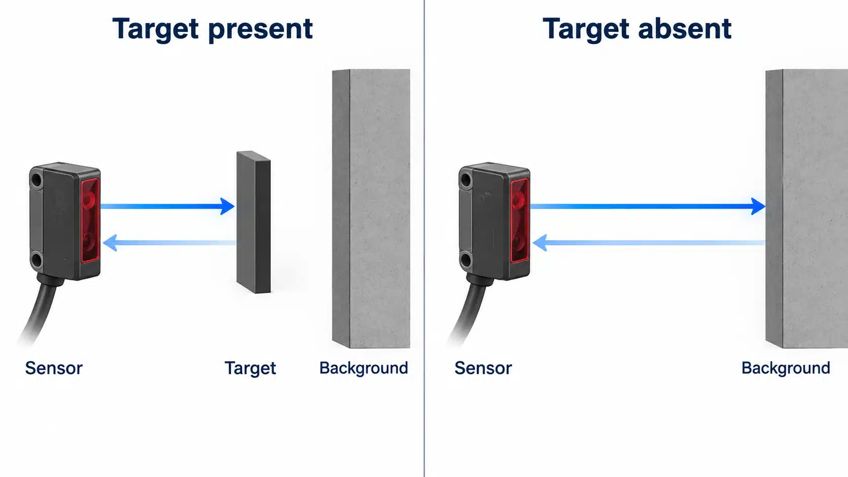
For diffuse sensing, check what the sensor sees after the object leaves. A conveyor, bracket or nearby machine surface may return light from the same direction. Testing only the target-present state misses this failure: the sensor may detect the intended object yet fail to recognise its absence.
Trace the complete permitted target movement. Include sideways displacement, tilt and the nearest background position. The trial should establish a distinct absent condition as well as a distinct present condition, without depending on a carefully held sample that cannot be maintained in production.
Compare Installation Access, Working Distance and Optical Margin
The optical method must fit the machine over its operating and maintenance cycle. A clear line of sight during assembly is insufficient if routine access, vibration or contamination changes it afterwards.
One-Sided Wiring Is Not the Same as One-Sided Installation
Retro-reflective sensing can avoid electrical wiring on the reflector side, but it still needs a secure place for that reflector. The surface must be accessible for alignment and cleaning. If a moving guard carries the reflector, its return position becomes part of the detection geometry.
A through-beam pair needs suitable positions for both units. Consider cable routing and connector access before choosing the smallest available mounting gap. Diffuse sensing removes the opposite optical component, but the resulting sightline must still avoid an indistinguishable background return.
Sketch the arrangement with the machine in its relevant positions. Mark the sensor, any opposite component, the full target path and the areas needed for servicing. This simple layout check can eliminate an unsuitable method before model specifications distract from the physical constraint.
Rated Distance and Useful Signal Margin
A sensing-distance figure describes performance under stated conditions. For diffuse sensing, those conditions include a reference target. A rating established with a white test target cannot simply be assigned to a small dark production component. Retro-reflective performance depends on the specified reflector, while a through-beam rating applies to a defined emitter/receiver arrangement.
Optical margin describes how far the useful signal is from a switching boundary. One related measure, excess gain, compares the received light with the sensor's switching threshold. Margin can help accommodate attenuation from gradual dirt accumulation or a modest alignment change, but its usefulness depends on preserving the difference between the two intended states.
More gain is therefore not an unconditional improvement. If a thin or translucent target leaves enough light at the receiver, increasing the available light may make the interrupted state harder to distinguish. Review the applicable curves and adjustments, then test both states. Do not apply a universal gain multiplier or treat the maximum catalogue distance as a dependable operating point for every target.
When Background Suppression Is Needed
Consider background suppression when diffuse sensing is mechanically attractive but target and background returns are difficult to separate by intensity alone. A weak target return and a strong background return can overlap, leaving no useful sensitivity setting that detects one while rejecting the other.
Background suppression adds distance-related discrimination. In a common triangulation-based design, light returning from different distances reaches different positions in the receiving optics. The sensor uses that geometric information to distinguish the intended detection area from a background farther away. This is a different criterion from simply accepting more or less returned light.
The practical question becomes whether all target positions remain in the intended detection area while the background remains sufficiently separated. Check the model's transition region, adjustment conditions and target-related limitations. Background suppression reduces a particular source of confusion; it does not guarantee detection of every small, shiny or transparent object, or reject a background occupying essentially the same required detection position.
Check Switching Logic and Signal Timing
A suitable optical arrangement still has to deliver the state the machine expects. Specify what the control system should recognise when the target is present and when it is absent before comparing output options.
Light-ON and Dark-ON Across the Three Methods
Light-ON and Dark-ON refer to the received-light condition. They are not universal synonyms for target present and target absent.
In a basic diffuse application, an arriving target supplies the return that was previously absent. In a basic retro-reflective or through-beam interruption application, the arriving target reduces a return or beam that was previously present. Consequently, the same Light-ON setting can correspond to different target conditions across these arrangements.
Write down the required target-present output and the required target-absent output, then check the selected sensor's truth table and settings. Confirm both at the receiving controller. This prevents a successful optical detection from being interpreted with the wrong control logic.
Output Compatibility and Target-Gap Timing
NPN/PNP output selection is an electrical interface decision, separate from the choice of optical method or Light-ON/Dark-ON operation. Match the documented output circuit and supply to the receiving input. Do not assume that two sensors with the same connector or housing have interchangeable electrical connections.
Timing also involves two transitions. The sensor must respond when the target changes the light, and recover when the next required optical state appears. Short gaps between objects can therefore matter as much as the objects themselves. Use the selected model's operation and release specifications and its stated switching-frequency conditions; a headline frequency alone does not establish an allowed line speed.
Then check the controller's input filtering and capture behaviour. A sensor indicator may appear to switch correctly while the input fails to recognise a short electrical state. Test the actual target spacing and production speed with the intended receiving channel, rather than accepting the indicator as the complete result.
Validate the Choice Under Real Operating Conditions
A useful trial should expose the reason a candidate might fail. Establish the expected target-present and target-absent states in advance so that the result is more precise than “the sensor detected the sample.”
Compare Target-Present and Target-Absent States
Set up representative mounting geometry and carry out adjustments with hazardous machine movement safely controlled. Use the equipment's documented operating limits and authorised test procedures.
- Establish the absent condition. Fit the intended reflector or receiver where applicable, and leave actual backgrounds in place. Confirm the sensor and receiving input indicate the expected state.
- Introduce the difficult samples. Include the weakest-return or least-occluding variants, not only the easiest sample. Move them through the permitted positional and angular extremes.
- Check the return to absence. Remove the target completely and confirm the output resets as required. Include reflective surroundings and any machine position that changes the optical path.
- Test normal motion and the shortest required gaps. Compare the receiving system's results with a known sequence of target events. Investigate discrepancies rather than adjusting sensitivity until one convenient sequence passes.
- Assess the permitted environmental variation. Include relevant ambient light, vibration and realistic optical contamination within the documented limits. Record the conditions, settings and any maintenance assumptions needed to retain reliable discrimination.
If changing sensitivity to solve one sample creates a false response in another condition, reconsider the optical arrangement or a more suitable detection function. Repeatedly tuning around overlapping states does not establish a robust operating range.
Information to Confirm Before Model Selection
Keep a concise application record: target material and dimensions; surface and transparency variations; target path and positional range; available mounting sides; sensor-to-target or sensor-to-counterpart distance; background position; required event rate and shortest gap; supply, output and receiving-input requirements; and relevant environmental exposure.
Use that record to request the exact model documentation and suitable accessories. Confirm any minimum-object specification against its test conditions, and agree what the sample trial must demonstrate. A shared housing style is not evidence that different sensing modes have the same performance.
For an XSZ enquiry, the rectangular photoelectric sensor range provides a product-family starting point. State the required optical arrangement and application conditions alongside the available installation space. The next decision should be a documented candidate and a meaningful sample test, rather than a model selected solely by appearance or maximum distance.
Technical Sources
- OMRON — Overview of Photoelectric Sensors: sensing arrangements and target-dependent optical behaviour.
- OMRON — Explanation of Terms: reference targets, response time and Light-ON/Dark-ON terminology.
- Pepperl+Fuchs — Frequently Asked Questions about Retroreflective Sensors and Reflectors: reflector compatibility, shiny targets and transparent-object selection.
- SICK — Background Suppression: distance-related background discrimination.
- Banner Engineering — What Is Excess Gain and How to Use It to Choose a Sensor: optical margin, attenuation and the limits of increasing gain.
- Banner Engineering — Photoelectric Sensors: corroborating descriptions of the sensing arrangements.