Description
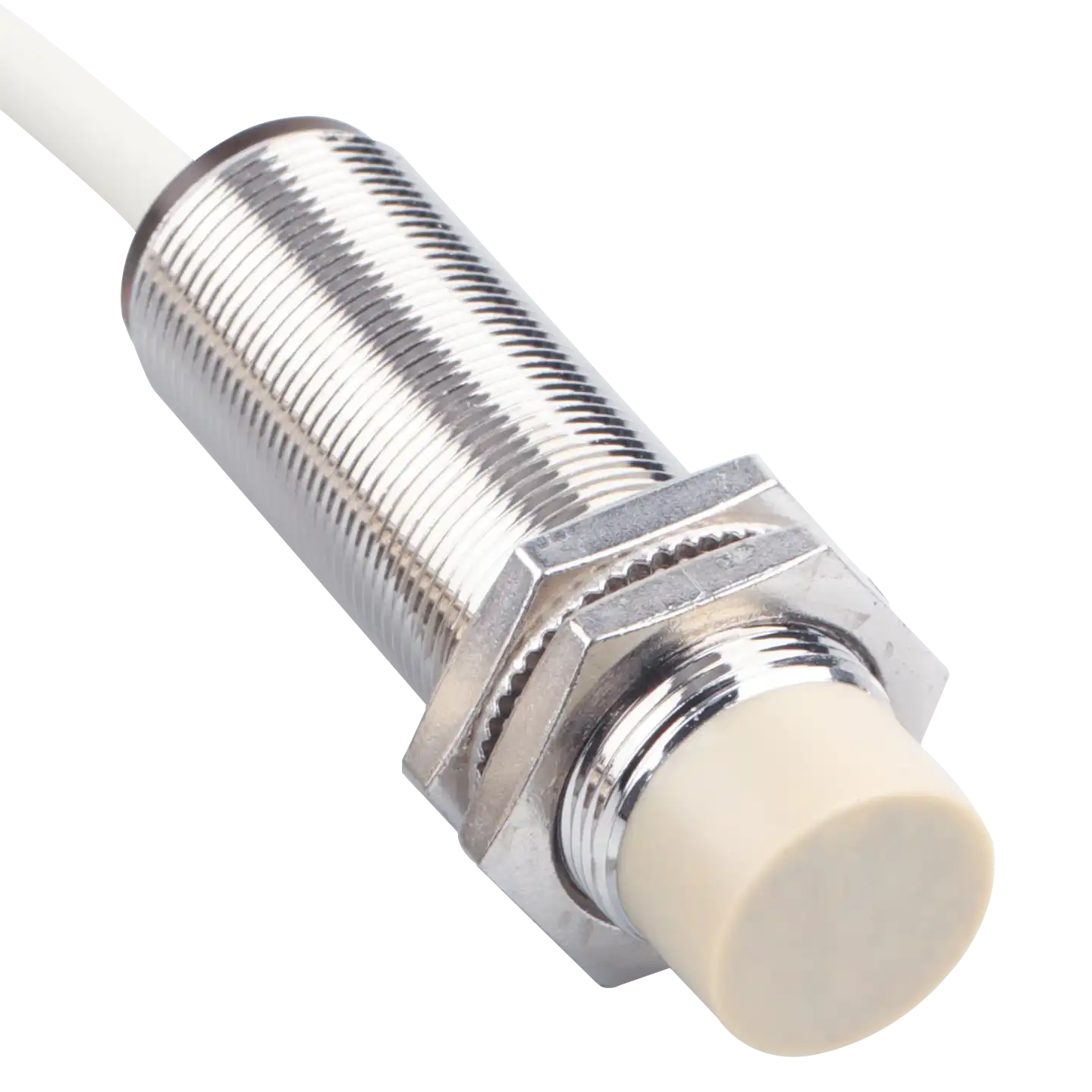
M30 cylindrical inductive sensor overview
The XSZ M30 cylindrical inductive proximity sensor series includes flush- and non-flush-mount configurations for metal-target detection. The flush configuration lists a 10 mm ±10% sensing distance; the non-flush configuration lists 15 mm ±10%. Each figure is based on its own standard iron target, so the two distances should not be compared without considering target size and mounting conditions.
The range lists NPN and PNP output options with normally open (NO) and normally closed (NC) logic. Confirm the exact part number for the required mounting configuration and controller interface before specifying a sensor.
| Family | M30 cylindrical inductive |
|---|---|
| Flush mount | 10 mm ±10% |
| Non-flush mount | 15 mm ±10% |
| DC supply | 10–30 VDC listed range |
Flush and non-flush sensing choices
The flush-mount selection is specified at 10 mm ±10% with a 40 × 40 × 1 mm iron target and 300 Hz response frequency. The non-flush selection is specified at 15 mm ±10% with a larger 54 × 54 × 1 mm iron target and 200 Hz response frequency.
Magnetic metal is the listed detectable-target category. The available information notes that sensing distance decreases with non-magnetic metals. Verify the actual workpiece material, dimensions, travel path and installation gap rather than assuming either nominal distance applies to every target.
Technical specifications
Use the configuration-specific figures with the actual target and mounting arrangement. Confirm a current model code and wiring diagram before making the controller connection.
Configuration comparison
| Specification | Flush mount | Non-flush mount |
|---|---|---|
| Sensing distance | 10 mm ±10% | 15 mm ±10% |
| Standard iron target | 40 × 40 × 1 mm | 54 × 54 × 1 mm |
| Response frequency | 300 Hz | 200 Hz |
| Exact model code | Confirm before ordering | Confirm before ordering |
Shared electrical data
| Operating voltage | 10–30 VDC; 12–24 VDC nominal |
|---|---|
| Supply ripple | 10% peak-to-peak maximum |
| Maximum output load current | 200 mA |
| Maximum residual voltage | 1.5 V |
| Maximum current consumption | 10 mA |
| Available output types | NPN or PNP; separate NO or NC versions |
| Protection circuit | Reverse-supply-polarity protection |
Operating environment and connection
| Operating temperature | −25 to +70 °C |
|---|---|
| Storage temperature | −40 to +80 °C |
| Connection | Pre-wired cable; confirm length and conductor assignment |
Applications and installation checks
An M30 inductive sensor can be evaluated for detecting the presence or position of a metal part in industrial equipment. Choose the mounting configuration around the available space and the required sensing gap, then test with the actual material and part geometry. Application suitability depends on the machine environment and the selected model.
Before specifying an M30 sensor
- Select flush or non-flush mounting, then verify the exact part number and full mechanical drawing.
- Confirm target material, size and gap against the configuration’s standard iron target.
- Choose the required NPN/PNP and NO/NC version for the controller; obtain its wiring diagram before energizing.
- Check output load, response frequency, cable length and environmental rating for the final model.
Frequently asked questions
What is the difference between the 10 mm and 15 mm versions?
The listed 10 mm ±10% figure belongs to the flush configuration and uses a 40 × 40 × 1 mm iron target. The 15 mm ±10% figure belongs to the non-flush configuration and uses a 54 × 54 × 1 mm iron target.
Will either version detect every metal at its nominal range?
No universal range is established. The values use specified iron targets, and the supplied information notes reduced distance for non-magnetic metals. Test the real workpiece and gap.
Can NPN, PNP, NO and NC be changed on one sensor?
The range mentions these as available output versions. Confirm the required model code; the available information does not establish them as on-device switchable settings.
What is needed before mounting and wiring?
Obtain the exact model code, mounting drawing and wiring diagram, then confirm the controller input, supply, load and target gap.