
Description
LJC30A3-H-ZBX product overview
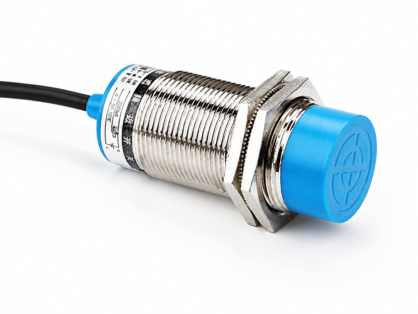
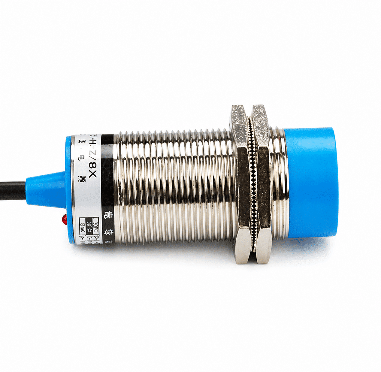
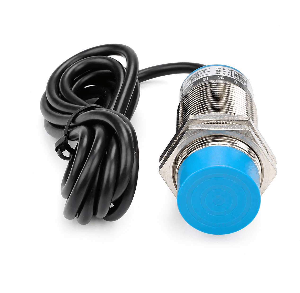
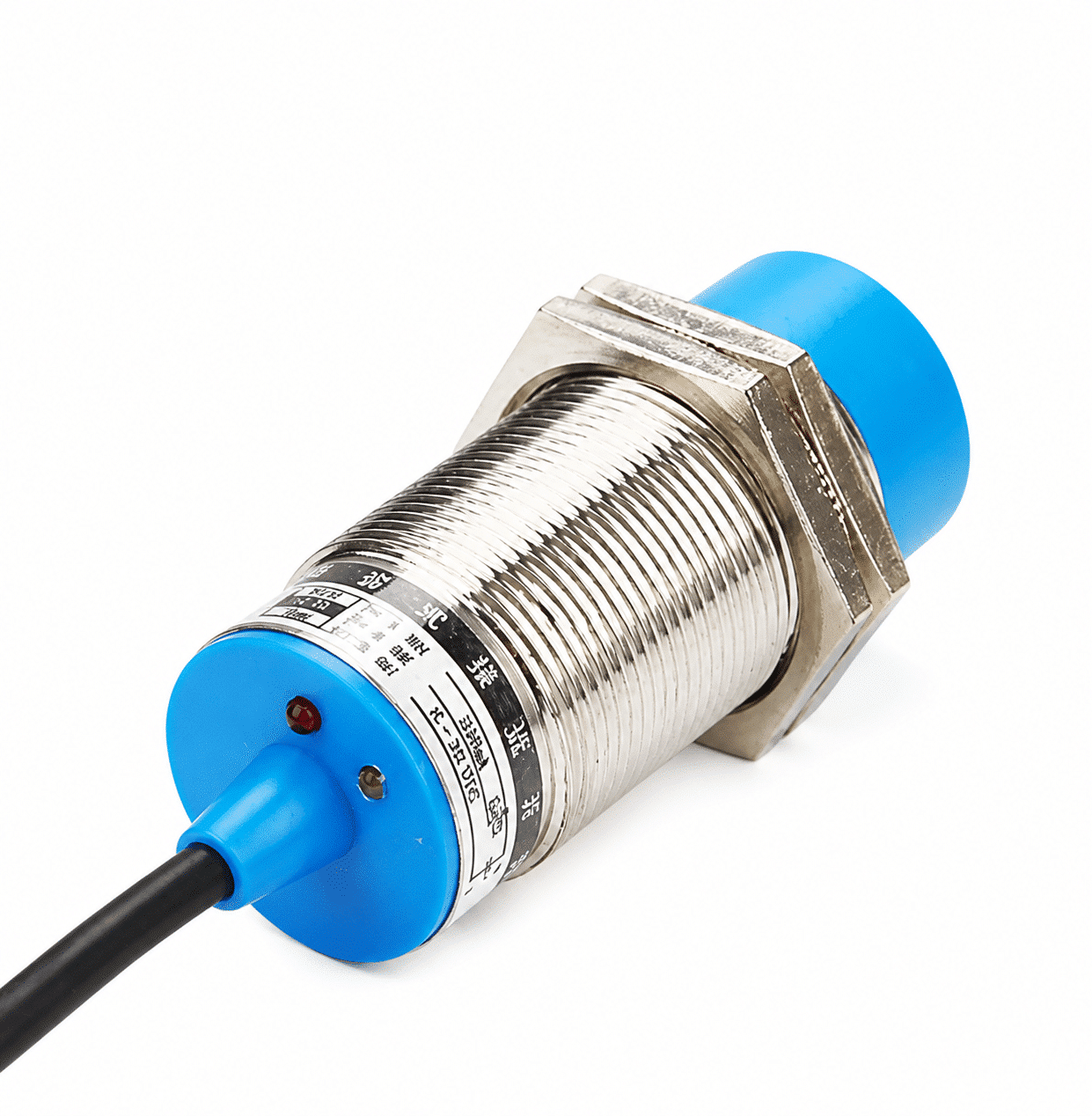
The XSZ LJC30A3-H-ZBX is the DC NPN normally open (NO) model in the supplied M30 non-shielded proximity-sensor range. Its listed 20 mm ±10% sensing distance is a target-sensing specification, while M30 describes the threaded body.
This model is intended for an installation that requires a non-shielded M30 sensor and an NPN NO input signal. Evaluate the actual target material, shape, approach direction and mounting environment against the current product data before committing to a detection point.
| Model | LJC30A3-H-ZBX |
|---|---|
| Body / installation | M30 × 1.5, non-shielded |
| Sensing distance | 20 mm ±10% (listed) |
| Electrical output | DC NPN, normally open |
20 mm non-shielded sensing and target selection
The legacy specification gives a 20 mm ±10% sensing distance and a 0–18 mm setting distance. The setting range is the more practical reference when planning the installed gap; the nominal sensing figure alone does not establish reliable detection for every target.
Target material and geometry affect selection. Provide a representative part and the intended sensing gap when confirming the application; the listed distance does not establish the same response for every production material or part shape.
Technical specifications
The following figures are from the M30 non-shielded range specification. Confirm the current exact-model datasheet and drawing for final machine design.
Sensing and mechanical data
| Product configuration | M30 non-shielded proximity sensor |
|---|---|
| Thread | M30 × 1.5 |
| Sensing distance | 20 mm ±10% |
| Setting distance | 0–18 mm |
| Hysteresis | Less than 10% of sensing distance |
| Action indicator | Red light, as identified in the supplied drawing |
DC NPN NO electrical data
| Output configuration | DC NPN, normally open (NO) |
|---|---|
| Listed DC supply | 12–24 VDC; source also shows 6–36 VDC in parentheses |
| Consumption current | Less than 13 mA (source N.P. DC group) |
| Response frequency | 0.5 kHz (DC type) |
| Insulation resistance | At least 50 MΩ at 500 VDC, between energized parts and housing |
Environment and materials
| Operating and storage temperature | −30 to +65 °C; no freezing or condensation |
|---|---|
| Humidity | 35–95% RH |
| Protection class | IP67 |
| Housing | Nickel-plated brass |
| Sensing face | ABS |
Related M30 non-shielded models
The supplied range table lists the current NPN NO model alongside separate NPN NC, PNP and AC two-wire model codes. Those are distinct electrical versions, not settings that can be switched on this unit.
| Electrical type | Logic | Legacy model code |
|---|---|---|
| DC NPN | NO | LJC30A3-H-Z/BX — catalog notation for this model |
| DC NPN | NC | LJC30A3-H-Z/AX |
| DC PNP | NO | LJC30A3-H-Z/BY |
| DC PNP | NC | LJC30A3-H-Z/AY |
| AC two-wire | NO | LJC30A3-H-J/EZ |
| AC two-wire | NC | LJC30A3-H-J/DZ |
Installation and selection checks
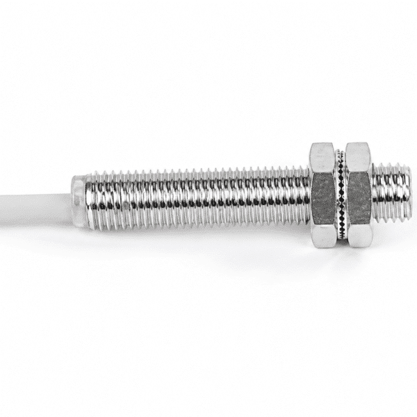
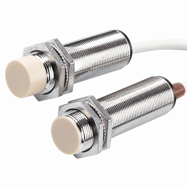
The source drawing describes an M30 × 1.5 threaded body with two clamp nuts, two buckle washers and a red action indicator. Obtain the current dimensional drawing to check sensing-face clearance, mounting position and cable exit before machining the bracket.
Confirm for your application
- Target material, dimensions and actual gap within the listed 0–18 mm setting range.
- DC supply and NPN NO input compatibility with the controller.
- Required switching speed, cable/wiring arrangement and mounting clearance.
- Temperature, moisture and other site conditions against the current datasheet.
Frequently asked questions
What does the 20 mm measurement mean?
It is the listed sensing distance, not the housing diameter. The separate body designation is M30, and the listed installation setting distance is 0–18 mm.
Is this the NPN normally open version?
Yes. The supplied range matrix maps the corresponding legacy code to the DC NPN NO selection. The other NPN, PNP and AC two-wire codes are different products.
Can I use the 20 mm figure for any target?
No universal target capability is established by the supplied data. Check the actual target material, size and mounting gap with a representative part.
What should be confirmed before wiring the sensor?
Confirm the current wiring diagram, supply range, controller input and allowable output load for this exact model. Cable and connector details were not specified in the supplied material.


Reviews
There are no reviews yet.