Industrial Automation Sensing
Detect parts, tabs and edges as they pass through a fixed optical gap. Choose the slot opening, mounting style and output to suit your machine.
Detection at a Fixed Gap
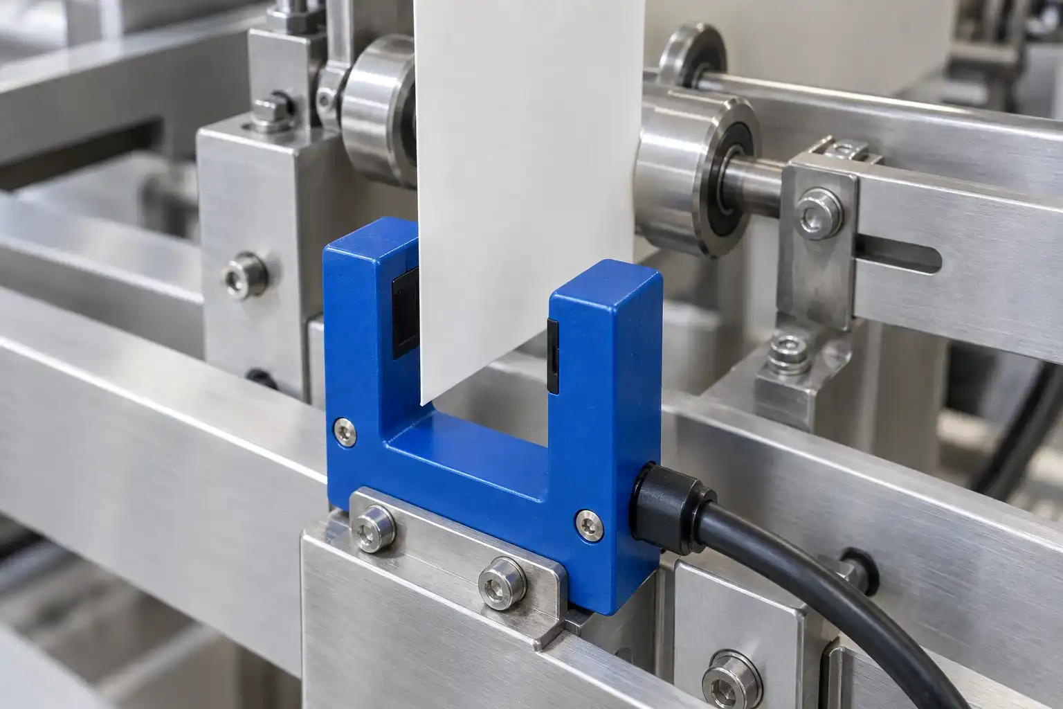
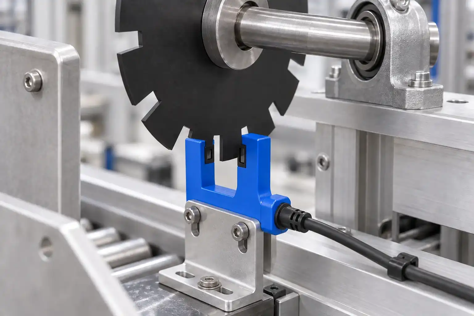
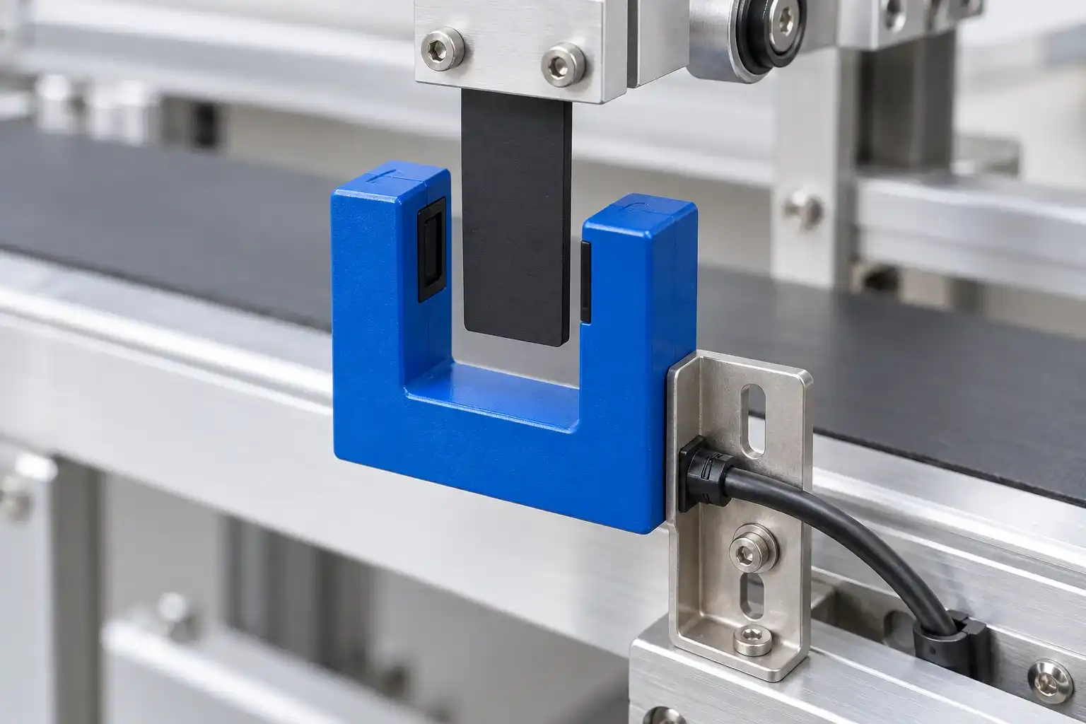
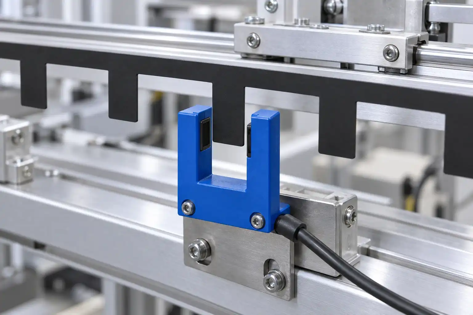
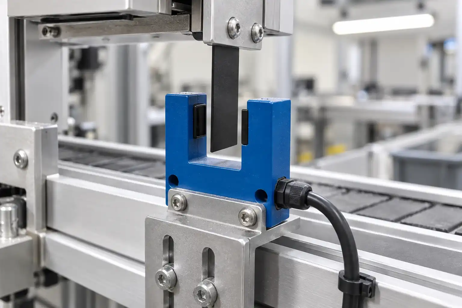
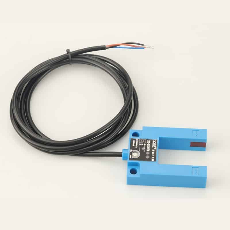
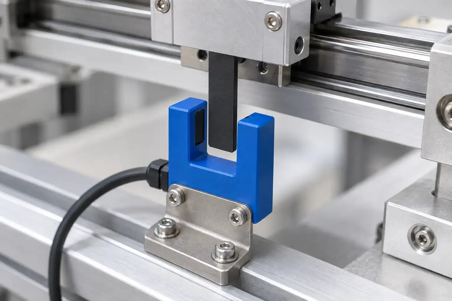
Slot photoelectric sensors place the emitter and receiver on opposite sides of a single fork-shaped housing. A target passing through the opening interrupts the light beam, providing a signal for presence detection, counting or positioning.
Allow clearance for the target and its movement without contact with the housing. Check whether the material blocks the beam, and match the sensor response and controller input timing to the passing speed. Transparent targets need testing rather than assumed compatibility.
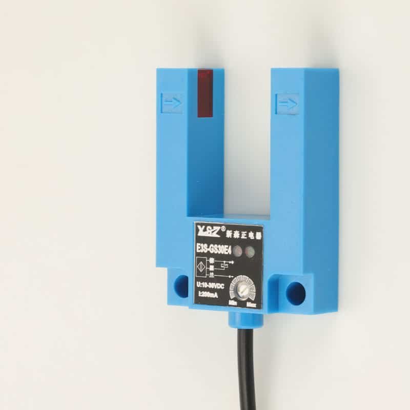
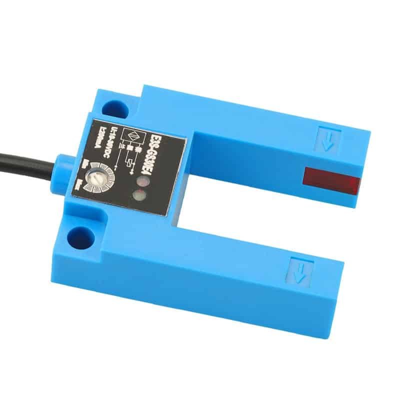
xsz sensor offers groove, compact and dual-channel options. Slot dimensions, supply voltage, output and switching logic must be confirmed for the selected model.
Our Product Range
Select by slot opening,
target path and wiring.
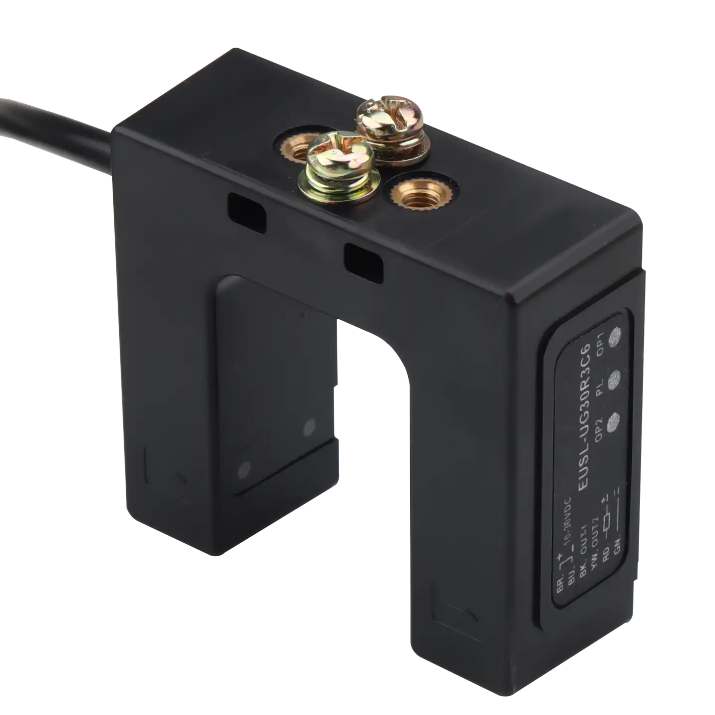
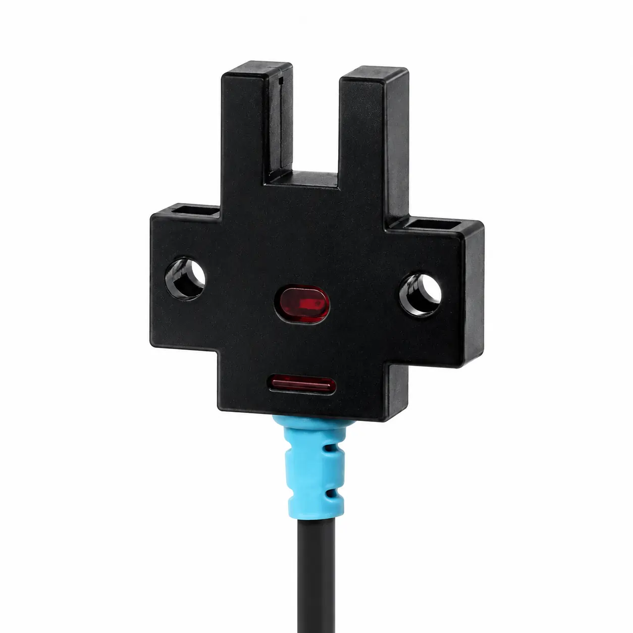
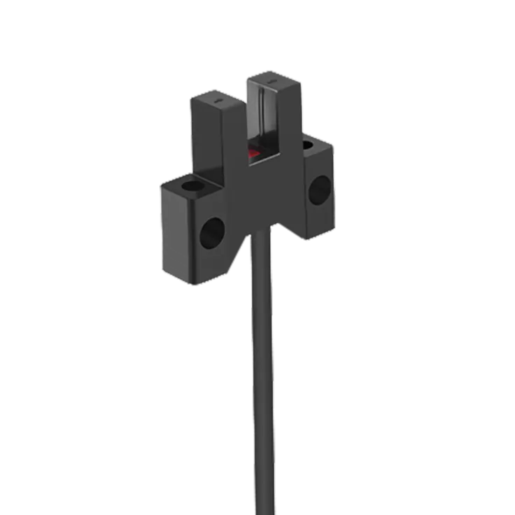

Share the target size, slot clearance, passing speed and controller input.
Find the right sensor for your application
Match the slot opening, target and switching response
to your machine's detection task.
Check slot width, depth and beam position. Allow room for target thickness and movement without touching either fork arm.
Check that the smallest target interrupts the beam. Clear film and translucent materials need testing with a suitable model.
Match sensor response to target speed and spacing. Check that the controller input can capture the shortest passing pulse.
Match fixing holes and cable direction to the machine. Verify supply voltage, NPN or PNP output and Light-ON or Dark-ON operation.
Compare selection options at a glance
Compare opening, mounting and signal requirements. Dimensions and functions depend on the selected model.
| Selection Profile | Main Focus | Mechanical Check | Target Check | Signal Check | Typical Use |
|---|---|---|---|---|---|
Compact Slot | Limited space | Body size and fixing-hole position | Flag size and path | Supply and output type | Small mechanisms, position flags |
Wide Opening | Target clearance | Slot width and sideways movement | Thickness and opacity | Light / Dark switching | Passing tabs, guided parts |
Deep Slot | Beam access | Slot depth and edge-to-beam reach | Edge position | Stable switching at full travel | Sheet edges, recessed paths |
Small Target | Fine features | Aperture position and alignment | Minimum target size | Pulse width and response | Small tabs, slotted discs |
Alternate Mounting | Mounting direction | Bracket fit and cable clearance | Entry direction | Pinout and controller input | Side-mounted machine assemblies |
Validate detection with real targets
Test the smallest target at its extreme positions. Confirm a clean change between beam clear and beam blocked.
Run at maximum speed and minimum spacing. Compare actual part counts with the pulses captured by the controller.
Check vibration, sideways drift and disc runout. The target must cross the beam without contacting the housing.
Check ambient light and dust at the optical windows. Verify switching after cable routing and final bracket tightening.
Bring the target through the optical slot
Keep the moving target clear of the fork arms and match the signal to your controller.
Align the target path with the beam position.
Verify available options in the model's datasheet.
Sinking output, when specified.
Match the controller input and load.
Sourcing output, when specified.
Check supply voltage and pinout.
Light-ON switches ON with the beam received. Dark-ON switches ON when the beam is interrupted.
Check the connection type and wire assignment. Leave room for cable routing and maintenance.
Slot photoelectric sensors place the emitter and receiver in one fork-shaped housing. Detect opaque tabs, edges or guided parts as they interrupt the beam, with clearance through the opening.

Use an opaque flag on a moving carriage to signal a selected reference position.

Guide an opaque sheet edge through the slot to confirm arrival or passage.

Pass disc openings and solid sections across the beam to generate pulses for a compatible controller.

Count individually guided opaque parts that fit the opening and fully interrupt the beam.
Match the target path to the slot and beam position. Confirm a clean change between beam clear and beam blocked throughout the machine cycle.

Allow clearance for drift and vibration. Keep the target crossing the beam without contacting either sensor arm.

Check the minimum target and beam position. Thin or translucent targets may not block enough light.

Check blocked and clear intervals against sensor response and controller input timing. Test the closest spacing at line speed.

Keep the optical windows clear. Validate the selected model under actual dust conditions and nearby lighting.
From application review to OEM supply, build a sensing solution around your production line.
Support from
selection to supply.
Review the target,
slot and signal.
Check the selected
configuration.
Validate on your
actual machine.
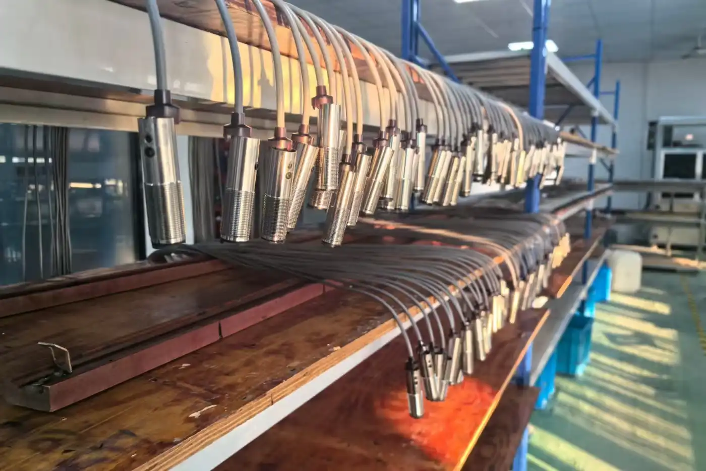
From production to inspection, every step is built for stable quality.

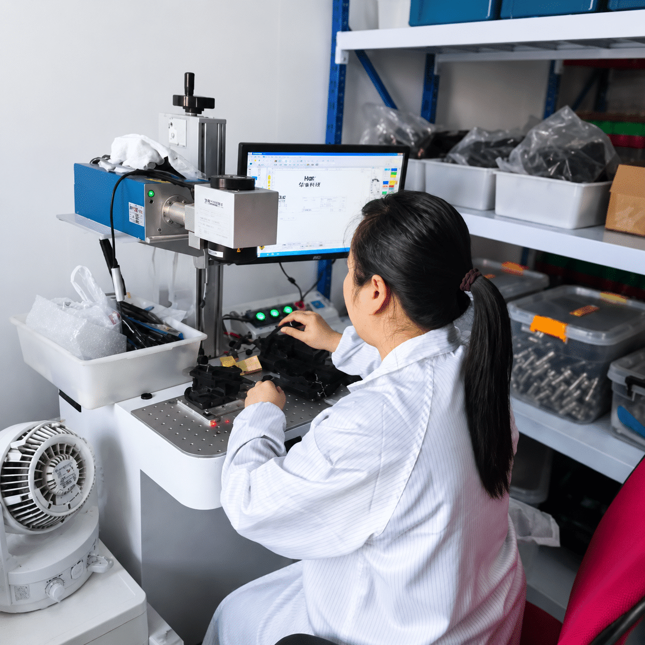





Flexible Solutions for Your Application
Share your target dimensions, movement path and mounting space. Our engineering team can review feasible configuration and branding options for your slot photoelectric sensor application.
Housing & Slot Size
Review slot width, slot depth and mounting space against your target path.
Detection Setup
Check the smallest target, beam position and the direction of movement through the slot.
Cable Length
Discuss cable length and routing for your machine layout.
Connection Type
Review available cable or connector options against your wiring requirements.
Output & Timing
Match available outputs and response performance to your controller and cycle speed.
Label / Branding
Discuss custom labels, logos and part numbers for your OEM project.
Explore More
Practical reading for slot sensor selection, small-part detection and installation.
Selection Guide
How to Choose a Slot Photoelectric Sensor
Review slot dimensions, target size, movement path and controller requirements.
Read ArticleSensor Comparison
Slot vs. Diffuse Photoelectric Sensors
Compare beam-interruption detection with reflective sensing for your installation.
Read ArticleApplication Guide
Detecting Small Parts with Fork Sensors
Check the minimum target, beam position and timing needed for repeatable detection.
Read ArticleCommon Questions
Quick answers to help you select and install a slot photoelectric sensor.
An emitter and receiver face each other across the slot. A target is detected when it interrupts the light beam. The output behavior depends on the selected model and its light-on or dark-on configuration.
Choose enough width for the target and mechanical clearance, and enough depth to reach the required detection point. Check the beam location and minimum detectable target separately; a wider slot does not automatically detect smaller objects.
For an opaque target that blocks the beam, surface color is usually less important than in reflective sensing. Light transmission, target size and the amount of beam interruption still matter, so test the actual material.
It depends on the model's minimum target and response specifications. Verify part spacing, beam position and the controller's input timing, then test repeated cycles at the actual operating speed.
Not every optical slot sensor can. Clear materials may transmit too much light for reliable detection. Use a model suited to the material or another sensing technology, and verify it with actual samples.
Place the target path across the specified beam position without touching the fork. Secure the sensor, keep the optical windows clean and check nearby light sources. Verify wiring and switching through the complete motion.
Let's Build a Smarter Tomorrow
Share your target size, movement path, cycle speed and controller requirements. Our technical team can help you review slot dimensions and detection setup.