
How to Choose a Slot Photoelectric Sensor for Small-Part Detection
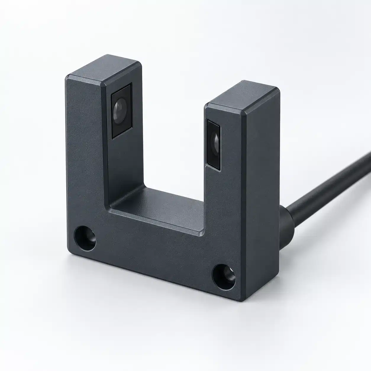
For small-part detection, choose a slot photoelectric sensor that can detect the required feature throughout its permitted travel, distinguish both targets and gaps at operating speed, and deliver signals the receiving input can capture. Slot width describes the opening; it does not establish the smallest detectable target or reliable counting speed. Confirm the exact configuration with documentation and a sample test of the complete detection chain.
Quick Selection Guide — Parameters to Confirm
| Selection check | Parameters or conditions to confirm |
|---|---|
| Detection task | Presence, individual count or a specific feature; acceptable and unacceptable target examples. Detecting a carrier does not prove that a smaller feature is present. |
| Slot geometry and target path | Slot width, depth, beam position and the complete movement envelope. Check both mechanical clearance and beam crossing, including permitted tilt and sideways variation. |
| Optical detection | Target material, smallest feature, orientation and position; minimum-object test conditions and any sensitivity setting. Do not treat aperture dimensions as a detection guarantee. |
| Target and gap timing | Maximum passage speed, shortest projected solid length and smallest clear gap. Estimate both intervals, then verify the electrical states; geometric estimates are not measured output pulses. |
| Sensor switching limits | Applicable operation/release limits and switching-frequency test conditions. An average frequency rating or slow-pass result does not establish dynamic performance. |
| Electrical interface and input capture | Supply, output circuit, switching logic, wiring and the exact receiving input; include filter settings and counting or event-capture behavior. |
| Environment and acceptance | Final mounting, lighting, contamination, temperature and cleaning exposure within documented limits; agree the reference count and acceptance criteria, then retain settings and test results. |
Use this guide to prepare a shortlist and an application test plan. It does not supply XSZ product ratings: unresolved values must be confirmed for the exact proposed configuration.
Define the Smallest Feature and Its Travel Path
A slot sensor, also called a fork sensor, places an emitter and receiver on opposite sides of one housing. This fixes their relationship, but the machine must still bring the intended feature through the sensing path. OMRON’s photomicrosensor overview describes slot devices and the importance of choosing the appropriate shape, connection and operating configuration.
Presence Detection or Individual Part Counting?
Write down the event you need to detect. “A carrier has arrived” and “one individual component has passed” can require different test conditions, even when the same component moves through the sensor.
Presence detection asks whether the target occupies the sensing location at the required moment. Counting asks the system to distinguish successive events. For counting, specify both the shortest solid feature along the direction of motion and the smallest clear gap between features. If adjacent parts remain optically joined, a single beam cannot identify their boundary from an uninterrupted blocked state.
Illustrative scenario: a guided carrier has a narrow locating tab followed by a longer body. A beam aimed at the body may confirm arrival but cannot establish that the tab itself is present. Place the detection point on the feature that answers the process question, then test acceptable and unacceptable parts there. These are different inspection tasks, not interchangeable sensor settings.
Opaque Parts, Translucent Targets, and Uncontrolled Paths
Start evaluation with the actual material and its least favorable intended orientation. An apparently dark plastic part may still transmit light at the sensor’s wavelength. Transparent or translucent targets therefore need a suitable sensing specification and sample testing; their visible appearance is insufficient evidence of compatibility.
Map the full movement envelope, including sideways drift, tilt and vibration. Check that the smallest relevant feature intersects the beam at every allowed position. A wider opening can provide more clearance without correcting a path that misses the sensing zone. If uncontrolled movement lets parts bypass or repeatedly cross the beam, improve guidance or reconsider the sensing arrangement before selecting a faster device.
Record the target drawing, material, dimensional tolerances, direction of travel and permissible movement. These inputs make slot photoelectric sensor selection a defined engineering task rather than a search for the smallest housing.
Choose Slot Geometry and Optical Resolution Separately
Mechanical fit and optical detection answer different questions. Use the drawing to establish where a target can travel, and the sensing specification to establish what the sensor can distinguish there.
Slot Width, Depth, and Beam Position
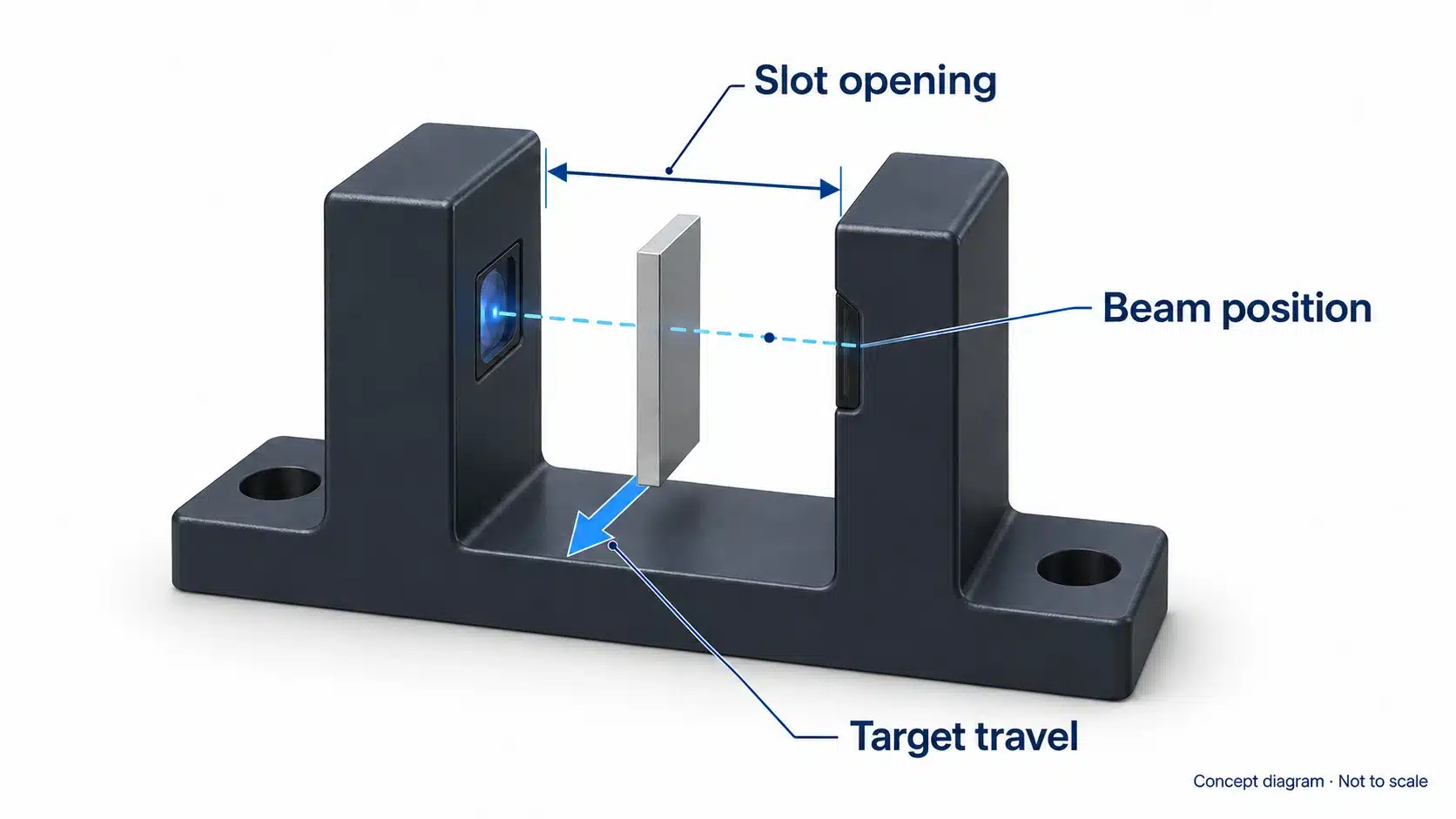
The slot width is the gap between the opposing faces. Some datasheets call this the sensing distance. It is not the minimum detectable object size. Slot depth describes the opening’s reach into the housing; the beam may sit at a specific offset within it. Check the manufacturer’s dimension arrows because the reference edges matter. OMRON defines these sensing and timing terms in its photomicrosensor terminology guide.
Use these distinctions when comparing candidate drawings and datasheets:
| Item | What it tells you | What to verify for the machine |
|---|---|---|
| Slot width | Space between the fork faces | The complete moving envelope clears both sides |
| Slot depth and beam location | Reach and sensing position relative to the housing | The required feature crosses the beam before another surface obstructs travel |
| Beam or aperture dimensions | The documented optical opening or sensing geometry | Its orientation relative to the target and direction of motion |
| Minimum detectable object | A detection result for a specified target and test setup | Target shape, opacity, position, gain and motion conditions |
| Switching behavior | How an optical change becomes an electrical state | Both transitions meet the application and input requirements |
Do not treat a drawn optical aperture as a guaranteed minimum-object specification. It helps locate and orient the sensing region; actual switching also depends on how much light reaches the receiver and where its switching threshold lies. Ask for the target test conditions when the datasheet provides only a drawing.
Minimum Detectable Object and Its Test Conditions
Published examples show why a single size value can be misleading. For its SLM10 models, Banner lists a minimum rod diameter of 1.00 mm at maximum gain and 0.30 mm at twice excess gain. The test passes the rod slowly through the beam midway between emitter and receiver. Those conditions, including the gain setting, are part of the specification; they do not establish detection at production speed. See the SLM manual, revision H, page 3.
OMRON’s EE-SX95 specification, on a page dated March 2, 2015, gives a 5 mm slot width and an opaque 1.8 × 0.8 mm minimum sensing object. A rectangular target specification and a rod-diameter test are not equivalent comparisons. These examples explain how to read data; they are neither XSZ ratings nor recommendations to substitute one model for another.
Request minimum-object data for the intended target position and orientation, and record any sensitivity setting. Then verify moving targets and gaps: a successful slow pass does not establish dynamic performance.
Check the Timing of Both Parts and Gaps
Line speed alone is incomplete. The time available for detection depends on the dimension presented along the direction of travel, while the time available to separate two events depends on their clear spacing.
Estimate the Shortest Blocked and Clear Intervals
For an initial geometric estimate, use an opaque rectangular feature moving at constant linear speed through an ideal beam of negligible width:
- Blocked interval: t_block = L / v.
- Clear interval: t_clear = G / v.
Here, L is the projected solid length along travel, G is the clear gap behind it, and v is speed. With L and G in millimeters and v in meters per second, the numerical results are in milliseconds: 1 mm divided by 1 m/s equals 1 ms. The target must also be tall and opaque enough to interrupt the sensing path.
Illustrative calculation: let L = 1.2 mm, G = 0.6 mm and v = 1.5 m/s. The ideal blocked interval is 0.8 ms; the clear interval is only 0.4 ms. A system assessment based on the longer interval would overlook the tighter requirement. If motion or spacing varies, use the shortest credible interval for each state rather than the average feed rate.
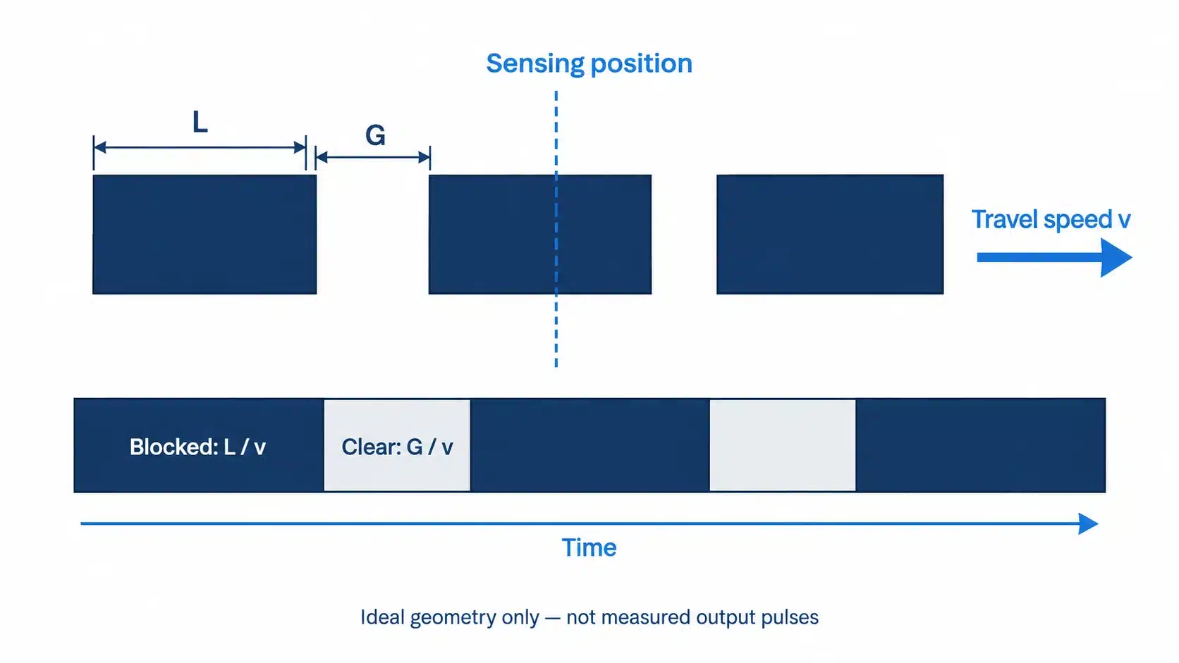
These are geometric estimates, not measured sensor output pulses. Finite beam size, target shape, switching threshold and unequal transition delays can change the electrical waveform. Do not subtract a generic “total delay” and declare a pass. Measure the output at the final input connection and compare both states with the requirements of the selected input path.
Response Time Is Not the Same as Switching Frequency
Response time describes the delay between an optical input change and the corresponding output operation or release. Response frequency describes repeated detection under specified test conditions. One number therefore does not fully describe the other, especially when the real blocked and clear intervals are unequal. The OMRON terminology guide distinguishes these definitions.
For example, the EE-SX95 page specifies 1 kHz minimum and 3 kHz average, with a rotating-disk test identified in its footnote. The average figure is not a guaranteed design limit, and that disk test is not your small-part conveyor. Keep the stated test basis attached to any comparison.
Ask the supplier for the relevant operation and release limits, any specified minimum input event durations, and the conditions used for the switching-frequency rating. Then test the shortest target and gap at the fastest intended passage. Choosing a sensor with a higher frequency rating does not establish that the downstream controller can register every transition.
Match the Sensor Output to the Controller Input
Treat the sensor, wiring and controller input as one signal path. A reliable optical transition is useful only if the receiving circuit recognizes the electrical levels and the control function captures the intended events.
NPN/PNP and Light-ON/Dark-ON Are Different Choices
For the transistor outputs discussed here, PNP sources current and NPN sinks current. Match the circuit to the actual input module and its common connection. Separately, in opposed-beam sensing, Light-ON activates the output when the beam is received; Dark-ON activates it when the beam is interrupted. These distinctions are documented in the Banner SLM manual and reflected in XSZ’s output selection guidance.
Specify the desired state for “part present” and “part absent” explicitly. Do not assume that a product described as NO or NC has the circuit type you need, or that switching the program logic makes an electrically incompatible output usable.
Before wiring, obtain the exact ordered model’s connection diagram. Check its permitted supply range, load limits, output voltage and leakage specifications against the input’s requirements, together with conductor assignments and connector pinout. A similar cable or model name is not a connection specification. Have the wiring checked by qualified personnel under the machine’s electrical procedures.
Input Filtering, Pulse Capture, and Counting
A short pulse may be present at the terminal but absent from the program’s sampled input state. Filtering and acquisition behavior are therefore part of selection, not commissioning details to leave until the end.
Siemens provides a useful specific example: its S7-1200 pulse-catch documentation places pulse catch after the input filter. A filtered-out pulse cannot be recovered by that latch. It also states that when multiple pulses occur within a scan, pulse catch reads only the first; it is not a complete event counter.
For repeated short events, evaluate a suitable counting or interrupt function using the exact controller manual. The documented S7-1200 high-speed counter input guidance still requires an appropriate input-filter setting. This example does not prescribe a filter value or controller architecture for every machine.
Separate the checks during a trial: first confirm a distinct sensor output for each target and gap, then compare those events with the controller’s count. If the waveform is correct but the count is wrong, inspect the receiving channel, filtering, event handling and program logic. If the waveform already merges or misses events, investigate the target path, optics and sensor response first.
Check Mounting, Contamination, and Environmental Limits
Use the final bracket and cable route for qualification. A hand-held sample centered in a clean slot is not representative of a machine that vibrates or accumulates residue. The useful question is whether the intended optical crossing survives the full operating envelope.
Build these checks into installation:
- Check clearance through the complete motion, including carrier variation, tilt and runout. The moving component must not touch the fork arms.
- Locate the actual beam from the model drawing or housing indication, then verify the smallest target at the extremes of its permitted path.
- Secure the bracket and provide cable strain relief so routine movement or maintenance does not disturb the sensing position.
- Leave access to inspect and clean the optical windows using the manufacturer’s permitted method. Include expected contamination and nearby lighting in the trial conditions.
- Compare the exact model’s temperature, ingress-protection, vibration and material-compatibility documentation with the installation and cleaning conditions. Do not infer these limits from housing appearance.
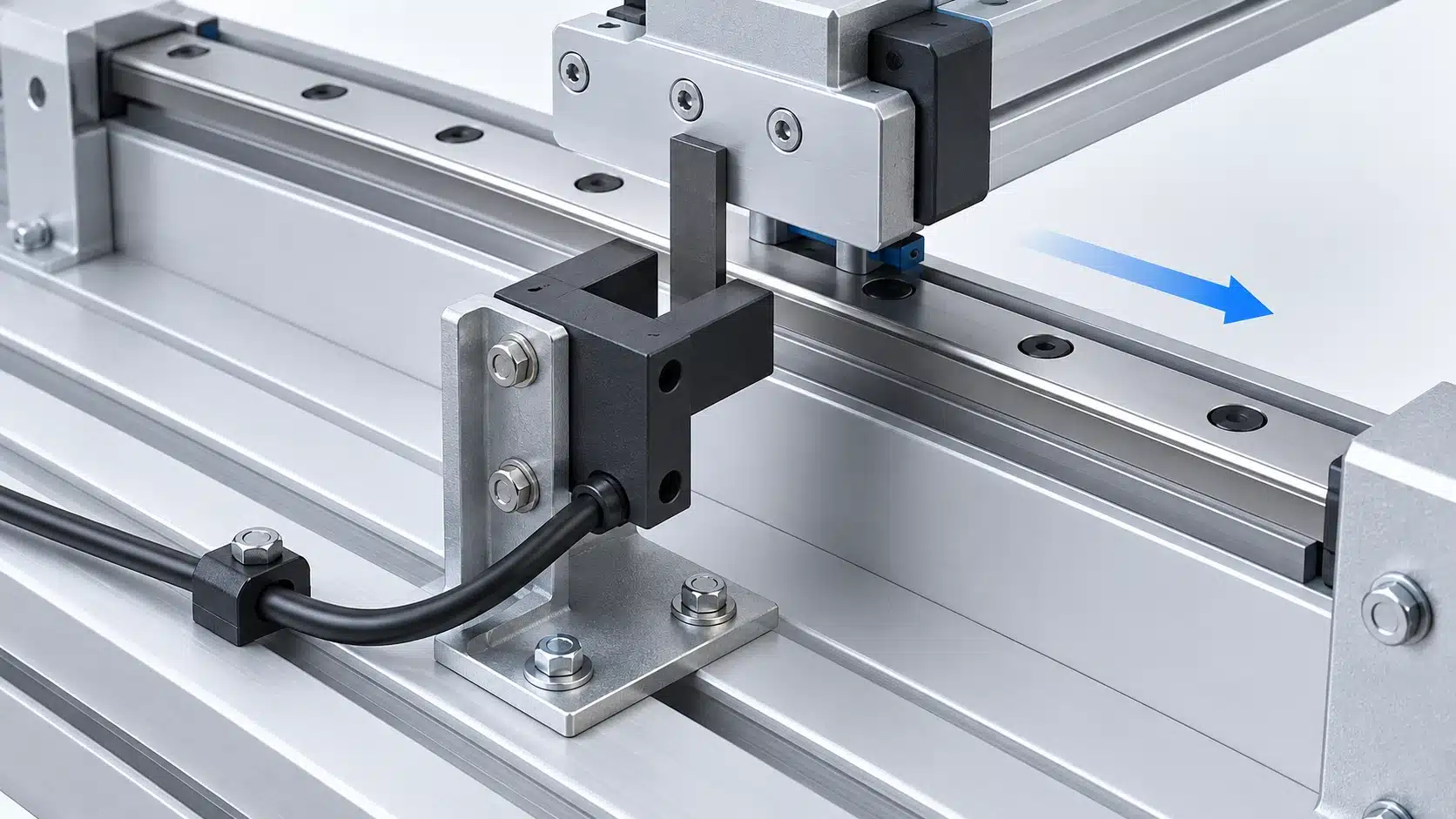
Treat these as qualification checks, not completed test results. If the installation needs conditions that the model documentation does not support, obtain a suitable documented configuration before committing to the mounting design.
This guide concerns process detection and counting. It does not establish suitability for personnel protection. Banner explicitly excludes that use for the SLM devices cited above in its safety warning; no safety qualification for an XSZ model is established here.
Build a Supplier-Ready Specification and Validate Samples
Turn the selection work into an application sheet that a supplier and machine builder can evaluate together. This separates what the machine requires from what a candidate sensor has actually demonstrated.
What to Confirm Before Choosing an XSZ Model
The XSZ E3S-GS30 product page is a real catalog starting point for a slot-sensor inquiry. Its listing is not enough to confirm the smallest detectable target, high-speed capability or electrical configuration for your application. Obtain the current drawing and technical details for the exact unit proposed, then compare them with the application sheet.
| Requirement to provide | Information to record | Selection checkpoint |
|---|---|---|
| Detection event | Presence, count or a specific feature; acceptable and unacceptable examples | The beam detects the feature that answers the process question |
| Target and path | Material, minimum feature, orientation, tolerances and motion envelope | Mechanical clearance and optical interruption both pass |
| Timing | Maximum passage speed, minimum solid length and minimum gap | Both states can be resolved by the sensor and receiving input |
| Electrical interface | Supply, exact input module, required output and logic, connection drawing | Voltage, current, wiring and event capture are compatible |
| Environment | Temperature, light, contamination, vibration and cleaning exposure | The ordered configuration is documented and tested for the intended conditions |
| Acceptance record | Test conditions, reference count, allowable errors and retained settings | Supplier and user agree what constitutes acceptance |
No XSZ minimum-object value, response time, pinout or environmental rating should be filled in from another manufacturer’s example. If the proposed configuration has an unresolved requirement, keep it open until the relevant documentation or agreed test resolves it.
An Acceptance Test for the Complete Detection Chain
Use the following as a proposed application test, adapting the duration, sample range and acceptance criteria to the consequence of a missed or extra detection. It is not a report of an XSZ factory or customer test.
- Agree the test basis. Identify the exact sensor configuration, target variants, machine settings and input channel. Define how an independent reference will establish the true part count, and agree allowable missed and extra events before testing.
- Check the installed geometry. With the machine in a safe setup condition, verify clearance and beam crossing throughout the permitted movement. Include the smallest relevant feature and the least favorable intended orientation.
- Establish static optical behavior. Confirm distinct target-present and target-absent states at the path extremes. Record any sensitivity setting. Reject a candidate that cannot separate the required states before attempting a speed trial.
- Run the timing cases. Under controlled, guarded operation, test the highest intended speed and shortest spacing, plus relevant start, stop and feed variations. Have qualified personnel use suitable instrumentation and safe access to observe both electrical states at the receiving input.
- Compare events and counts. Check sensor pulses and controller results against the independent reference. Record missed events, extra events and any merged pulses separately so the failure can be located rather than hidden in a net count.
- Repeat relevant operating conditions and freeze the setup. Check the agreed lighting, contamination and mechanical conditions within documented limits. Retain the wiring, filter and counter settings, mounting position, sample identification and observed results with the accepted specification.
A finite sample test establishes performance only for the conditions and samples evaluated; it is not a lifetime guarantee. Use the results to resolve the open requirements and define what must be rechecked after a target, sensor or machine-setting change.
Send XSZ the target samples or drawings, movement path, speed and spacing, exact controller input and installation conditions through the customized sensor requirements page. XSZ describes requirements review, feasibility assessment and sample evaluation. Use that process to agree a configuration and validation plan, and resolve open limits before production selection.