
What Are the Common Types of Sensors and Their Applications?
Common sensor types include proximity, photoelectric, ultrasonic, position, temperature, pressure, level, flow, force, vibration, humidity, and gas sensors. They turn a physical condition into information a machine or monitoring system can use. The right starting point is the question you need answered: Is a part present? How hot is the process? Is liquid moving? What load is being applied?
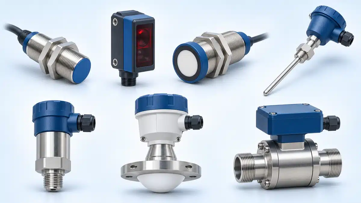
This guide connects those questions to common sensing methods and applications, with examples from industrial equipment, process systems, and environmental monitoring.
Quick Guide to Common Sensor Types and Applications
Use this table to find the task closest to yours. The groups are practical labels, rather than mutually exclusive categories: an ultrasonic device, for example, may serve a distance or level application.
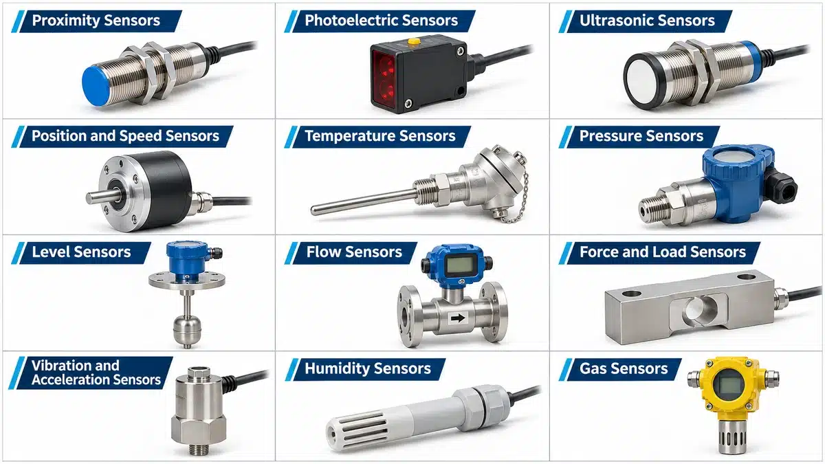
| Sensor family | What it detects or measures | Typical application | Decisive condition |
|---|---|---|---|
| Proximity | Nearby object presence or an end position | Metal parts, material presence, magnetic position feedback | Target material or magnetic field must suit the principle |
| Photoelectric | A change in received light | Packages crossing a conveyor, parts interrupting a slot beam | Optical arrangement, target surface, and background |
| Ultrasonic | Returned or interrupted sound | Noncontact distance or level monitoring | A usable sound path and, for reflective sensing, a sufficient echo |
| Position and speed | Linear or angular position, movement, or speed | Shaft feedback and machine-axis monitoring | Required position information, mounting, and motion |
| Temperature | Temperature at a sensing point or viewed surface | Process heating, cooling, and machine monitoring | Measurement range, thermal contact or optical access |
| Pressure | Pressure of a liquid or gas | Pneumatic, hydraulic, and process monitoring | Medium, pressure range, and process connection |
| Level | A material reaching a point or its changing level | Tank refill, high-level indication, inventory monitoring | Point detection versus continuous measurement |
| Flow | Fluid movement, flow rate, or a related flow condition | Cooling-water circulation and compressed-air monitoring | Medium, required flow quantity, and pipe installation |
| Force and load | Applied force or load used for weighing | Checkweighing and press-force monitoring | How the force reaches the sensing element |
| Vibration and acceleration | Mechanical acceleration and oscillation | Monitoring motors, pumps, or bearings | Measurement range, frequency coverage, and mounting |
| Humidity | Water vapor in a gas, often expressed as relative humidity | Storage conditions, drying, and HVAC monitoring | Temperature and exposure to the air being assessed |
| Gas | A specified gas concentration or a defined gas-response signal | CO2 or VOC monitoring in air-quality systems | Substance, sensing principle, and meaning of the output |
The type name narrows the search. Understanding what causes its signal to change is what helps you decide whether it belongs on your machine.
How Are Sensor Types Classified?
What a Sensor Detects vs. How It Works
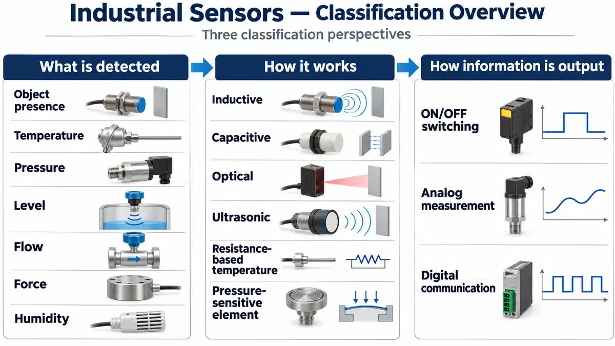
Sensor names often describe different things. Temperature, pressure, and level describe the quantity or condition being observed. Inductive, capacitive, and photoelectric describe how the device senses it. Output terms describe how that information leaves the device.
Consider the word capacitive. A capacitive proximity sensor responds to a target changing the electrical capacitance around its sensing face. A capacitive humidity sensor uses a material whose electrical properties change as it absorbs or releases water vapor. Both use capacitance, but one answers an object-detection question and the other measures an environmental condition.
This overlap also explains why catalogues group products differently. A broad use of proximity sensor can include several noncontact methods, while a catalogue may put inductive, photoelectric, and ultrasonic products in separate sections. Read the function and principle together rather than treating the catalogue heading as a complete specification.
Switching Outputs vs. Continuous Measurement
A switching output reports whether a defined condition has been reached. A part-presence sensor might change state when a target arrives. A pressure switch might change state at a pressure threshold. These signals help a controller make a discrete decision.
A measurement output provides a value instead: the pressure, distance, temperature, or another quantity within the instrument’s measuring range. That value lets the controller follow a trend or compare several operating conditions, rather than knowing only whether one limit has been crossed.
Digital does not automatically mean ON/OFF. A digital communication interface can carry numerical measurements and diagnostic information. Equally, a sensing element that changes resistance may need excitation and signal conditioning before a controller can interpret it. Identify the information required first, then choose a compatible output and receiving input.
Sensors for Object Detection, Position, and Motion
These devices help equipment recognize where something is or how it moves. Their differences become clearer when you follow the interaction between the target and the sensing element.
Inductive, Capacitive, and Magnetic Proximity Sensors
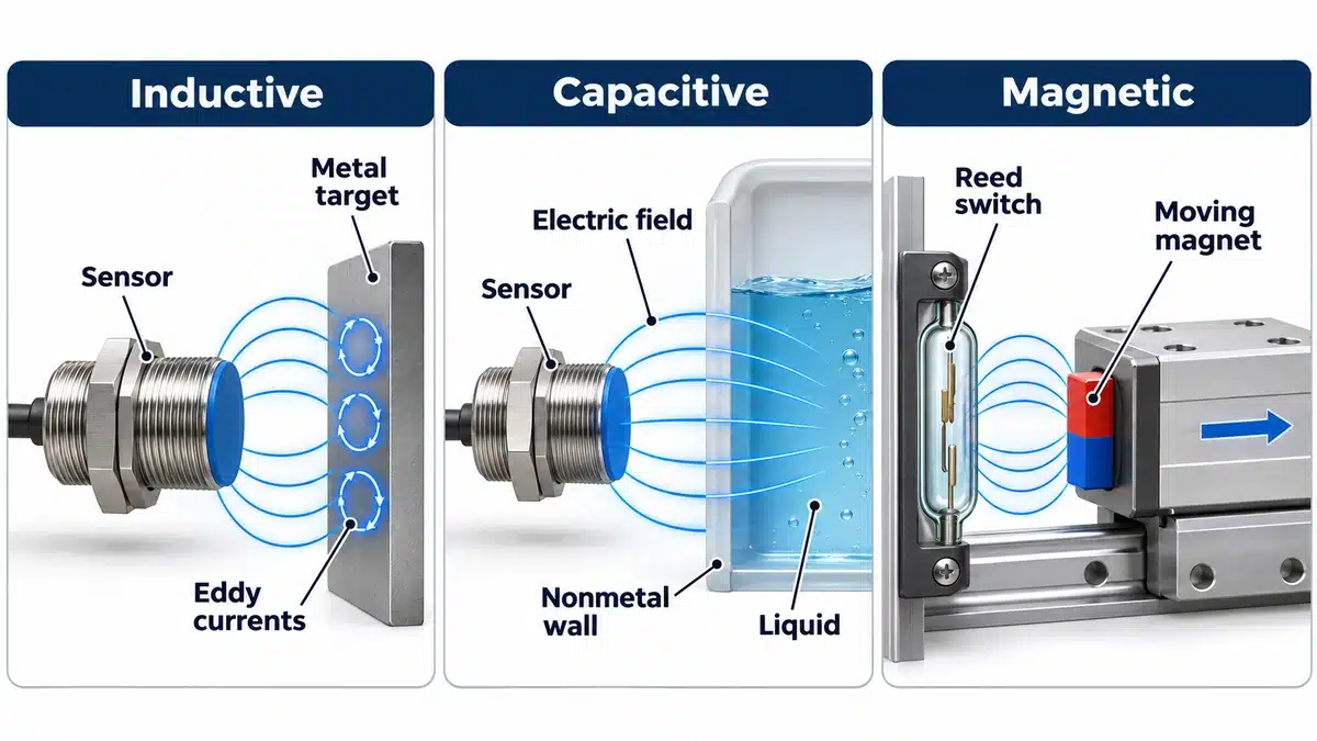
An inductive sensor generates an alternating magnetic field near its sensing face. A metal target entering that field changes the electrical behavior of the sensing circuit through induced eddy currents. Once the evaluated change reaches the switching point, the output changes state. The target does not have to touch the sensor.
A metal bracket passing close to a fixed sensing face is a useful starting application for inductive proximity sensing. Changing the bracket’s material, size, or path can change the usable detection gap, so a successful test with one metal part does not establish the same performance with another.
Capacitive sensing responds to capacitance changes. It can suit appropriate nonmetal targets as well as metals, including some liquid or bulk-material applications. The surrounding material contributes to the electric field too. A container wall and its contents therefore need to be considered together when the task is to distinguish empty from filled.
Magnetic sensing responds to a magnetic field. In a reed-switch implementation, a nearby magnet operates the contacts. This provides a way to detect a moving component carrying a suitable magnet. A plain metal part is a different target; choosing a magnetic switch simply because the part is metallic would miss the operating principle.
Photoelectric Sensors
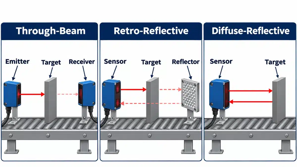
A photoelectric sensor uses an emitter and a light receiver. A target changes how much light reaches the receiver by interrupting a beam or returning light toward it. This makes optical sensing useful for detecting packages and components that need not be metallic.
The light path determines the installation. A through-beam arrangement places emitter and receiver on opposite sides. A retro-reflective arrangement sends light to a reflector and receives the return. Diffuse sensing receives light returned by the target itself. These arrangements place different demands on access, alignment, target surfaces, and background separation.
For a guided small part, a slot photoelectric sensor holds the emitter and receiver in one housing. The feature to be detected must pass through the beam, while the moving assembly clears the housing. The slot opening describes available space; it does not, by itself, establish the smallest feature the sensor can detect.
Ultrasonic Sensors
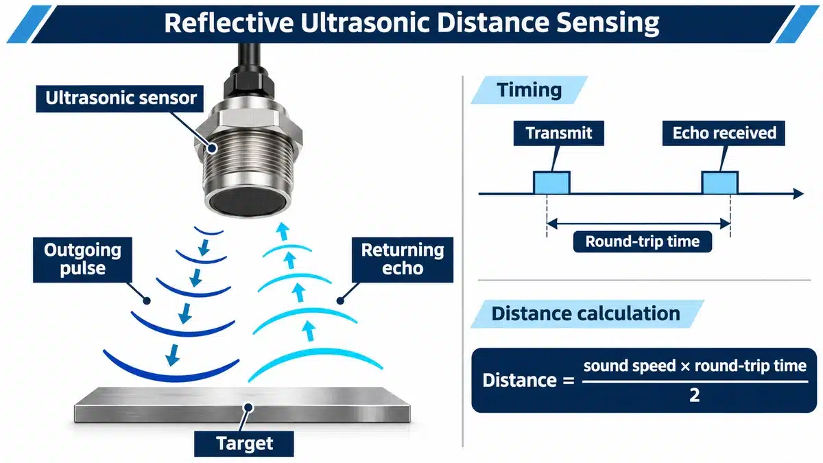
A reflective ultrasonic sensor sends a sound pulse toward a target and receives an echo. The travel time gives information about distance. Other ultrasonic arrangements detect an object interrupting sound between separate transmitting and receiving units.
Because the interaction is acoustic, an object’s color is not the same obstacle it may be for an optical return. This can make ultrasound a useful candidate for distance or level tasks where target appearance varies. It still needs an operable sound path. A reflective arrangement must receive a usable echo, and a target inside the device’s unstable near range is not a reliable measuring point.
The practical question is therefore more specific than “Can it detect this color?” It is whether the target returns enough sound throughout the required movement and whether that movement stays inside the usable operating range.
Position and Speed Sensors
A sensor that reports one end position answers a limited question: has the component reached this point? Continuous position feedback tells the controller where the component is across a range of travel.
A rotary encoder illustrates the difference. It converts shaft rotation into signals representing angular movement or position. By evaluating changes over time, a control system can also determine rotational speed. Incremental and absolute encoders provide different forms of position information, so their receiving and evaluation requirements differ.
On a machine, this distinction separates detecting that an axis has arrived from following its movement. Choose the required information before comparing housings. A compact presence switch and an encoder may both relate to position, but they provide different feedback and cannot be substituted solely because each responds to motion.
Sensors for Temperature, Pressure, Level, and Flow
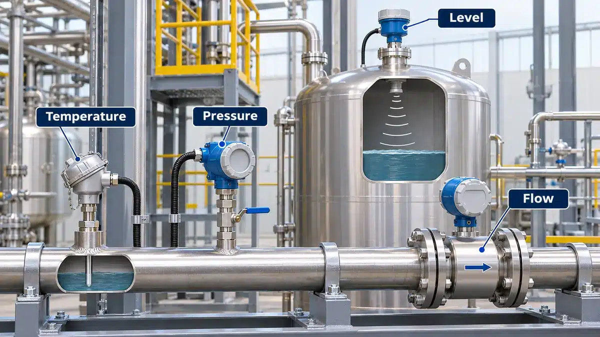
Process sensors describe the condition of a machine, vessel, or moving fluid. Several may be installed close together while measuring quantities that must remain distinct.
Temperature Sensors
Temperature sensors use a physical property that changes with temperature. An RTD, or resistance temperature detector, uses a metal element’s resistance. A thermistor also changes resistance with temperature, using a different sensing material. A thermocouple produces a small voltage related to the temperature difference between its measuring and reference junctions; the measurement system accounts for the reference-junction temperature.
These contact methods are used in probes for processes and equipment. The sensor must respond to the temperature at the intended location, which makes thermal contact and installation important. An infrared instrument instead detects radiation and estimates temperature without touching the viewed surface.
For a cooling circuit, the first decision might be where to measure the fluid temperature. For a moving surface, optical access may make a noncontact method attractive. The sensor type follows that measurement problem, together with the required range and response; there is no single temperature technology that is best for every installation.
Pressure Sensors
Pressure is force acting over an area. Many electronic pressure sensors use a sensing structure that deforms under pressure, with electronics converting the response into a signal. Pneumatic systems, hydraulic equipment, and process lines use that information to follow operating pressure or recognize a pressure limit.
The same application can need different outputs. A switching signal may answer whether pressure has reached a selected threshold. A measured value shows how pressure changes during operation.
Pressure does not establish flow by itself. A line can remain pressurized while fluid movement has stopped. If the requirement is to detect loss of cooling circulation, pressure information alone may leave the central question unanswered. Start with the quantity that matters, then select the pressure range, compatible wetted materials, and process connection when pressure is the required measurement.
Level Sensors
Level sensing answers how far a liquid or bulk material has filled a container. A point-level device detects whether material has reached a particular position. Continuous level measurement follows level across a range. The first can trigger a refill decision; the second can show the changing level between limits.
Different principles can serve this task. Capacitive sensing evaluates an electrical change near the material. Hydrostatic measurement relates the pressure produced by a liquid column to its height, with liquid density affecting that relationship. Radar or reflective ultrasonic instruments can use a returned signal to assess distance to the material surface.
The application determines which relationship is usable. A change of liquid density matters to a hydrostatic conversion. A poorly returned signal matters to a reflective method. Naming the task “level measurement” is the beginning of selection, rather than a reason to assume every level instrument behaves alike.
Flow Sensors
A flow sensor detects or measures a fluid moving through a system. Depending on the instrument, the useful result may be a flow condition, velocity, volumetric flow rate, or mass flow rate. These are related quantities, but they are not interchangeable labels.
A thermal flow method uses heat transfer: moving fluid carries heat away from a heated sensing region, and the instrument evaluates that cooling effect. This can support circulation monitoring, provided the instrument suits the medium and operating conditions. Other flow instruments use different physical relationships.
For a cooling-water line, define whether you need a low-flow indication or a measured delivery rate. For compressed air, identify the required gas-flow quantity and reference conditions. Then assess the pipe installation and medium compatibility. A tank-level reading describes stored material; it does not directly tell you the flow through a particular pipe.
Sensors for Force, Vibration, Humidity, and Gas
Other sensing tasks concern mechanical loading, equipment movement, or the surrounding atmosphere. These signals can reveal conditions that presence and process measurements do not describe.
Force and Load Sensors
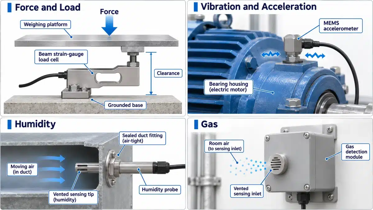
Force sensors measure an applied push, pull, or load. In a strain-gauge load cell, the applied force slightly deforms an elastic body. Gauges bonded to that body change electrical resistance as it deforms. A bridge circuit and measurement electronics turn the change into usable load information.
This supports applications such as checkweighing and press-force monitoring. The mechanical path is part of the measurement: the intended force must reach the sensing structure in the manner the device is designed to measure.
A package on a conveyor makes the distinction easy to see. A presence sensor can report that the package arrived, while a weighing system determines its weight from the load measurement. Neither signal supplies the other’s full answer. Other force-sensing technologies exist, so the strain-gauge explanation is one common implementation, not a definition of every force sensor.
Vibration and Acceleration Sensors
An accelerometer responds to acceleration. In one MEMS implementation, microscopic movable and fixed structures form a capacitor; movement changes their relationship and produces an electrical measurement. Such devices can capture mechanical vibration when their range and frequency response suit the motion.
Motor, pump, and bearing monitoring use these measurements to look for changes in machine behavior. The instrument must capture the acceleration amplitudes and frequencies of interest. A range that is too small can clip the signal, while insufficient bandwidth can leave relevant motion outside the measurement.
A changed vibration reading is evidence to investigate, rather than a complete diagnosis of one specific fault. Its meaning depends on what was measured, how the sensor was mounted, and the machine’s operating condition.
Humidity Sensors
Humidity concerns water vapor in a gas. Relative humidity expresses vapor pressure relative to saturation at the same temperature, which is why temperature is part of interpreting the reading.
A common capacitive implementation uses a polymer that absorbs or releases water vapor. Its electrical properties change, altering the measured capacitance. This supports monitoring air conditions in storage areas, drying processes, and heating, ventilation, and air-conditioning systems.
The sensor needs to sample conditions representative of the air you want to assess. A reading near a local heat source can differ from conditions elsewhere, and temperature changes affect relative humidity. This is a different task from detecting liquid in a tank, even when both devices happen to use a capacitive principle.
Gas Sensors
Gas sensing starts with the substance and the information required. An instrument intended to measure carbon dioxide, or CO2, performs a different task from a device that reports a response to volatile organic compounds, or VOCs.
One CO2 method evaluates absorption of selected infrared wavelengths by the gas. A metal-oxide VOC device instead evaluates a change in the sensing material’s electrical behavior when exposed to gases. The principle, calibration, and processing determine what the resulting output means.
For air-quality monitoring, distinguish a measured concentration of a specified gas from an index or broader response. Those outputs should not be treated as interchangeable simply because both devices are called gas sensors. The design of protective gas-detection and emergency alarm systems is outside this overview.
How Different Sensors Work Together in an Application
Consider an illustrative filling line, rather than a documented customer installation. A container travels to a filling station, receives product, and moves onward for a weight check. The line also has a supply tank and pneumatic equipment.
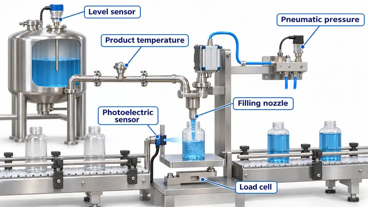
A photoelectric sensor reports that a container has reached the station. That is useful for the arrival decision, but its output does not establish how much product is inside. A load measurement at the weighing station addresses that separate question.
A level instrument on the supply tank indicates a refill point or follows the available material level. It does not directly confirm the amount delivered into each container. A pressure sensor describes the pneumatic supply condition, while a temperature sensor follows a relevant product or process temperature.
These signals complement one another because they describe different parts of the operation. If a filled container is underweight, the presence signal can still be correct. The next investigation concerns delivery and weighing conditions, rather than assuming the arrival sensor failed. If tank level falls, that observation is useful, but it does not replace a measurement of flow through the filling line.
The lesson is to define what each detection point must prove. A collection of individually working sensors becomes useful only when their signals answer the machine’s actual questions.
How to Choose a Sensor for Your Application
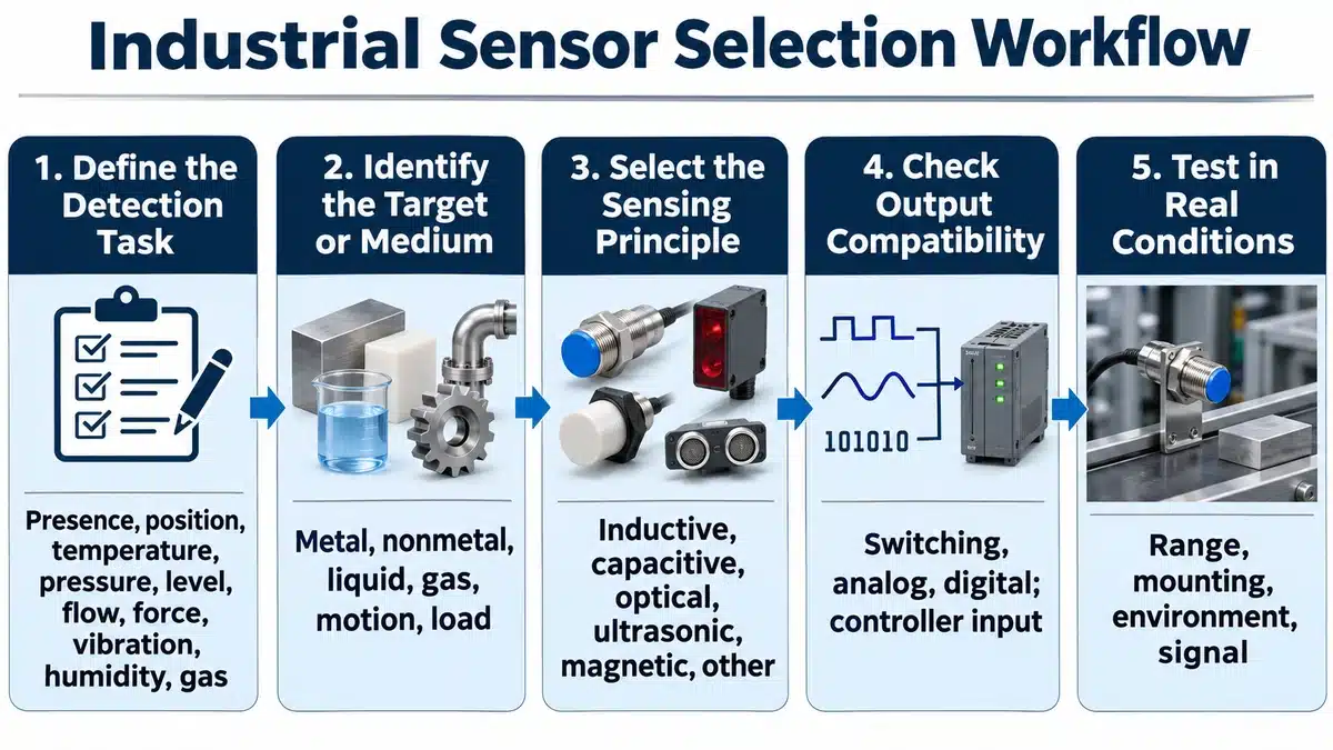
Define the Event or Quantity You Need to Detect
Write the required answer in plain language before choosing a technology: “A metal bracket has reached this position,” “The tank needs refilling,” or “The controller needs the pressure value during this cycle.” These requirements lead to different initial candidates.
Distinguish detecting a limit from measuring a range. If only an end position matters, a switching device may provide the necessary information. If the controller must follow movement between endpoints, it needs suitable position feedback. This decision prevents comparing devices that solve different problems despite having similar names.
Match the Sensing Principle to the Target and Environment
Next, look at the physical interaction. A close metal target makes inductive sensing a plausible starting point. If the task changes to detecting a nonmetal package across an open conveyor, the material and geometry point toward a different family, such as an appropriate optical arrangement.
Identify the condition most likely to challenge the choice. For a reflective optical setup, compare the actual target and background. For a capacitive material detector, assess the relevant wall, contents, and nearby materials together. For a process instrument, establish which medium contacts the sensor and what conditions it experiences. These observations help reject unsuitable methods before spending time on output options.
Match the Output to the Controller and Test the Result
Once the physical principle fits, match the information and electrical interface to the receiving system. A switching input needs a compatible switching output. A measurement channel must be able to interpret the sensor’s signal and scale it to the intended quantity. A shared connector shape does not establish either relationship.
Test the selected device with the actual target or medium and the intended controller. For detection, observe both target-present and target-absent states across the permitted movement. For measurement, compare readings with an appropriate reference across the required operating range. Include the variations that motivated the selection, rather than repeating only the easiest bench condition.
If your requirement concerns object detection, the XSZ proximity and photoelectric categories provide a starting point for a more detailed discussion. Describe the target material and size, movement, available mounting space, and information the controller needs. Those details turn a broad sensor-family choice into a model-selection question that can be evaluated.
Technical References
- TE Connectivity — Types of Sensors: sensor functions, output forms, and broad families.
- OMRON — Proximity Sensors: inductive, capacitive, and magnetic detection principles.
- OMRON — Photoelectric Sensors: optical paths and target detection.
- OMRON — Ultrasonic Sensors: reflected and interrupted sound.
- ifm — What Are Encoders?: position and speed information.
- NI — Measuring Temperature with Thermocouples, RTDs, and Thermistors: contact measurement and signal conditioning.
- ifm — Temperature Sensors: temperature methods and industrial applications.
- ifm — Pressure Sensors: pressure monitoring and output functions.
- ifm — Level Sensors: point and continuous level measurement.
- ifm — Hydrostatic Level and Density Measurement: the pressure, liquid-height, and density relationship.
- ifm — Thermal Flow Principle: flow-dependent heat removal.
- TE Connectivity — Load Cell Technologies: deformation, strain gauges, and force signals.
- Analog Devices — MEMS Accelerometers for Condition Monitoring: acceleration range and frequency limitations.
- Sensirion — Sensing Technologies: capacitive humidity, VOC, and CO2 sensing examples.
- Sensirion — Design Guide for Humidity and Temperature Sensors: humidity fundamentals and installation effects.