DC voltage
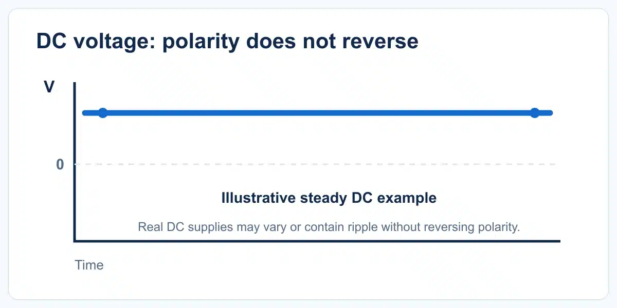
Direct-current supply has a defined polarity. Its value may vary within a specified range or contain ripple; “DC” does not mean perfectly constant. Many control circuits and industrial sensors use a DC supply.


Sensor Terminology
Meaning, Types and Importance for Sensors
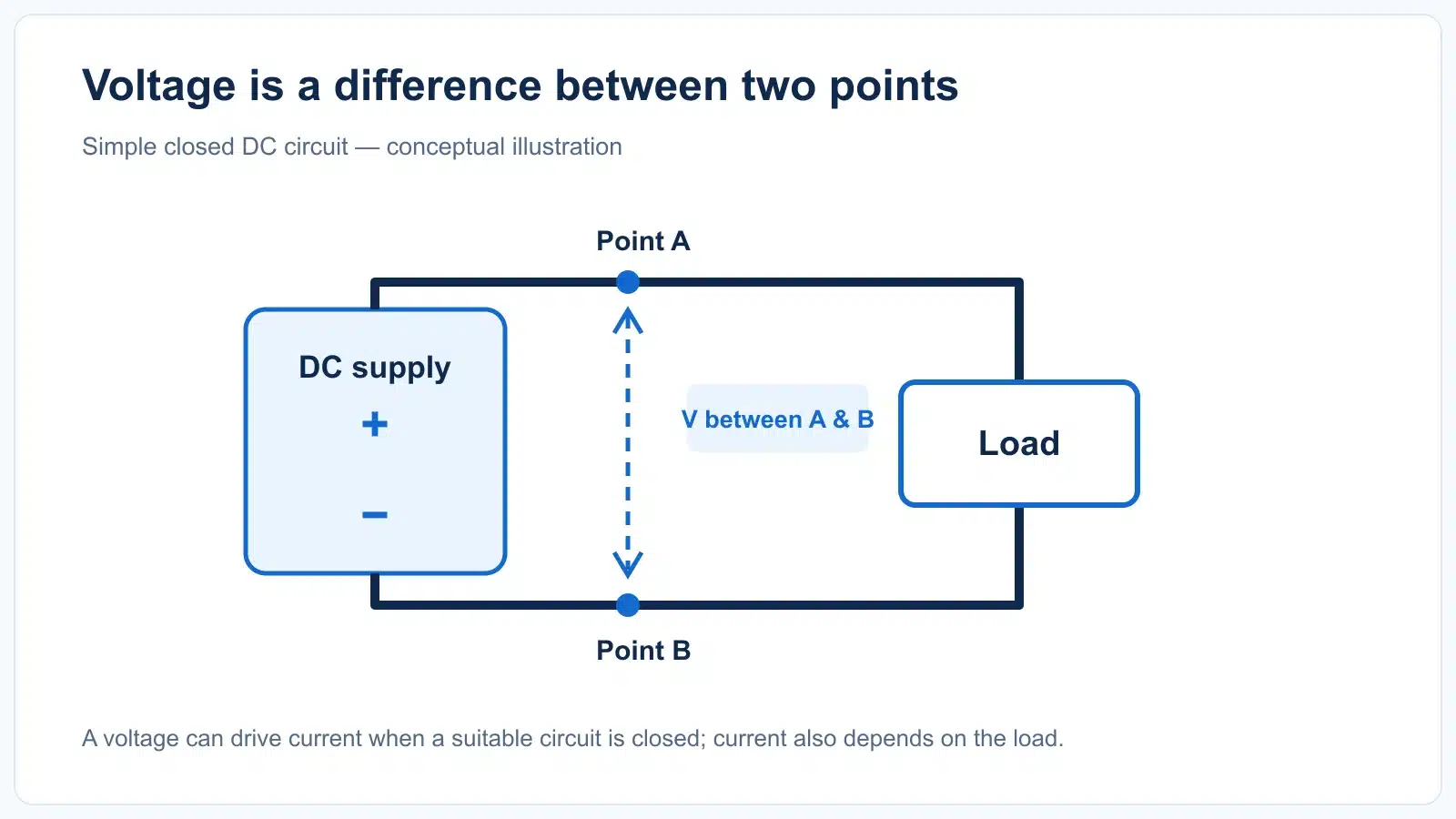
Voltage is the electrical potential difference between two points. For an industrial sensor, the right supply voltage is a basic requirement—but its output and the connected PLC input must be checked separately.
Voltage, measured in volts (V), is the difference in electric potential between two points. One volt represents one joule of energy per coulomb of charge. A voltage across a suitable closed circuit can drive electric current; the resulting current also depends on the circuit and its load.
Think of water pressure as a rough analogy: a pressure difference can move water through a pipe, just as a potential difference can drive charge through a circuit. It is only an analogy—electrical behavior also depends on resistance, impedance and circuit design.
The electrical supply can be DC or AC. A sensor's rated input range tells you which supply it is designed to accept.
Direct-current supply has a defined polarity. Its value may vary within a specified range or contain ripple; “DC” does not mean perfectly constant. Many control circuits and industrial sensors use a DC supply.
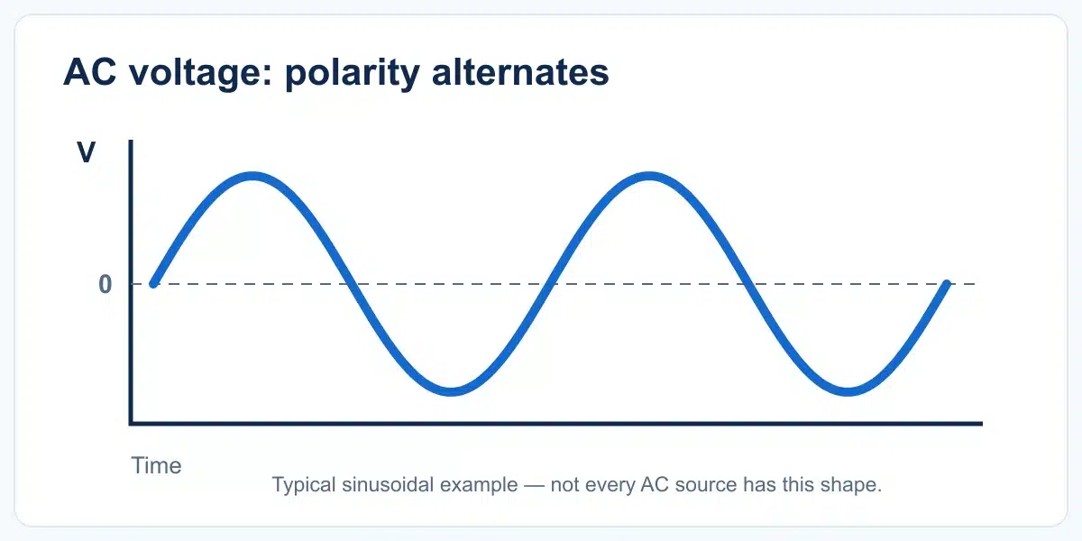
Alternating voltage reverses polarity periodically. AC-rated equipment also specifies a frequency, commonly 50 or 60 Hz for mains-powered equipment. Do not infer that a DC sensor can use AC because the machine itself is AC-powered.
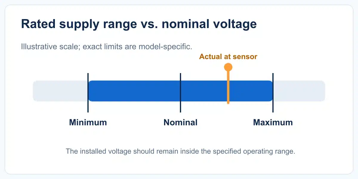
The operating range gives the allowed voltage at the sensor terminals, not just the nominal number printed on a power supply. Check the exact model's minimum, maximum and any ripple limits.
These are examples of supply labels you may encounter—not universal ratings or permission to substitute one supply for another. The exact sensor datasheet controls the decision.
| Example label | What it indicates | What to verify |
|---|---|---|
| 12 V DC | A nominal 12-volt direct-current supply. | Whether the exact sensor's DC operating range includes the actual voltage at its terminals. |
| 24 V DC | A common nominal control-system supply; it is not a rating shared by all sensors. | Sensor range, polarity, available current and connected controller input. |
| 10–30 V DC | An example of a model-specific permitted DC range, rather than one fixed voltage. | Include supply tolerance, ripple and voltage drop in the installed circuit. |
| AC supply rating | Some sensor models accept AC; others are DC-only. | The exact AC voltage range, frequency, output/load limits and wiring diagram. Never connect a DC-only sensor directly to mains. |
The sensor needs a supply within its rated range at its terminals, including when the machine is running.
An undersupplied or noisy circuit can produce unreliable operation; check the manufacturer's power requirements.
Supply voltage alone does not establish output compatibility. Confirm NPN/PNP or other output type, load limits and PLC input specification.
Exceeding the rated voltage or using the wrong supply type or polarity can damage a sensor and create a safety hazard.
These terms answer different questions. Confusing them is a common reason a sensor and PLC fail to work together.
| Specification | Question it answers | Example of what to check |
|---|---|---|
| Supply voltage | What powers the sensor? | Rated DC/AC range, polarity, current consumption and permitted ripple. |
| Output type | How does the sensor switch or communicate a detection? | PNP, NPN, relay, analog or IO-Link—according to the actual model. |
| Output/load rating | What electrical load may the output drive? | Maximum current, residual voltage or voltage drop, leakage current and protection provisions. |
| PLC input | What signal does the controller recognize? | Input voltage thresholds, wiring/common arrangement and compatibility with the chosen output. |
Start with the exact part number and its datasheet. Compare the installed electrical system to the rated operating conditions, not just the nominal label.
Each application may combine an AC-powered machine with a separate DC control circuit. The sensor's own rated supply and output interface must still match the installed system.

Photoelectric or proximity sensors can detect cartons and position changes. Verify their supply and PLC-input interface independently of the conveyor motor supply.

Machine sensors may share a control supply. Check loaded voltage at the farthest devices and follow each model's wiring requirements.

A PLC input must recognize the sensor's output state. Supply voltage, output type and input thresholds are separate compatibility checks.
Voltage is electric potential difference between two points, measured in volts. Current is the rate at which electric charge flows, measured in amperes. The current drawn depends on the connected circuit; a voltage value alone does not tell you the sensor's current consumption.
Many industrial control sensors are DC-powered, and 24 V DC is a common nominal control-system supply. Actual sensor ratings vary by model: some accept a DC range around that nominal value, while other models use different DC or AC supplies. Read the exact datasheet.
Only if 12 V DC is within that exact model's specified operating range after allowing for supply tolerance and wiring losses. A “24 V DC” nominal system label alone cannot answer this.
No—never connect a DC-only sensor directly to AC mains. Only use the supply type, voltage range and frequency specifically stated for the exact model, following its wiring and safety instructions.
No. The output depends on its circuit type, state and load. NPN and PNP transistor outputs, relay contacts and analog outputs behave differently; the controller must be matched to the actual output specification.
Wiring, connectors and load current can create voltage drop. Check the voltage at the sensor under realistic load and compare it with the rated minimum; use a qualified person for measurements on energized equipment.
Too little voltage can prevent correct operation. Too much voltage, incorrect polarity or the wrong AC/DC supply can damage equipment and create hazards. Disconnect power and check the exact model's rating before changing the circuit.