
Ring Sensor Missed Counts: Causes and Setup Checks
To troubleshoot ring sensor missed counts, compare actual part passages with the sensor output and the count recorded by the controller. Find the first point where those records disagree. If a part passes without a usable output event, investigate the target, installation and sensor settings. If the output reaches the controller but the count falls behind, investigate input capture and counting logic before changing sensitivity.

This guide covers inductive ring sensors used to detect metallic parts in automated feeding equipment. A setup that works with widely spaced samples may behave differently during a production burst. Check both the active output duration and the interval between outputs, using the instructions for the exact sensor and receiving input. Increasing sensitivity or extending a pulse is useful only when it addresses the fault you have identified.
Quick Diagnosis: Find Where the Count Is Lost
Use the observed symptom to choose a starting point. These checks separate possible causes; a symptom alone does not prove that a particular component is faulty.
| What you observe | Check first | What the result tells you |
|---|---|---|
| The count differs from the number of commanded feed cycles | Establish how many parts actually crossed the sensing position during the same period | A failed feed or a different counting window can look like a sensor miss |
| A confirmed passage produces no distinct output event | Test the actual target and path, then inspect installation and documented sensor settings | The problem may be at detection or output processing, before the PLC input |
| Widely spaced parts count correctly, but closely spaced parts do not | Observe output active time, recovery time and the shortest event spacing | Events may be too brief to capture or may not remain separately distinguishable |
| Distinct pulses reach the receiving terminal, but the count is low | Check electrical input requirements, filtering, capture mode, count enable and reset logic | The fault may be in signal acceptance or counting rather than target detection |
| Errors appear after a stop, restart or part change | Compare mode, settings, target variation and the start of the counting window | A change in operating conditions may explain why the earlier test no longer represents production |
Before changing wiring, moving the sensor or clearing a feed path, isolate the relevant hazards using the machine's procedures. Qualified personnel should perform necessary live measurements with suitable equipment and run tests with the required guarding in place. A counting check is not a reason to reach into a running feeder or bypass an interlock.
Confirm the Part Passage Before Changing Sensor Settings
Separate Missed Detection from Feed and Counting Errors
Start by defining the event the machine is supposed to count. It might be one metal part passing forward through a ring, one completed feed cycle, or one part arriving at a downstream station. Those events are related, but they are not interchangeable.
A feed command does not establish that a part passed the sensor. Likewise, a passage at the ring does not prove that the part reached its final position. If the reference count comes from commanded cycles while the displayed count comes from detected passages, the difference may originate in feeding rather than sensing.
Use a known batch or another independent record of passages at the sensing position. Keep the reference and controller observations within the same start and end conditions. Record whether parts can reverse, recirculate, arrive together or remain in the tube when counting stops. A final batch total can hide a missed event if another event was counted twice, so investigate the event sequence as well as the total when possible.
Compare the Physical Part, Sensor Output and PLC Count
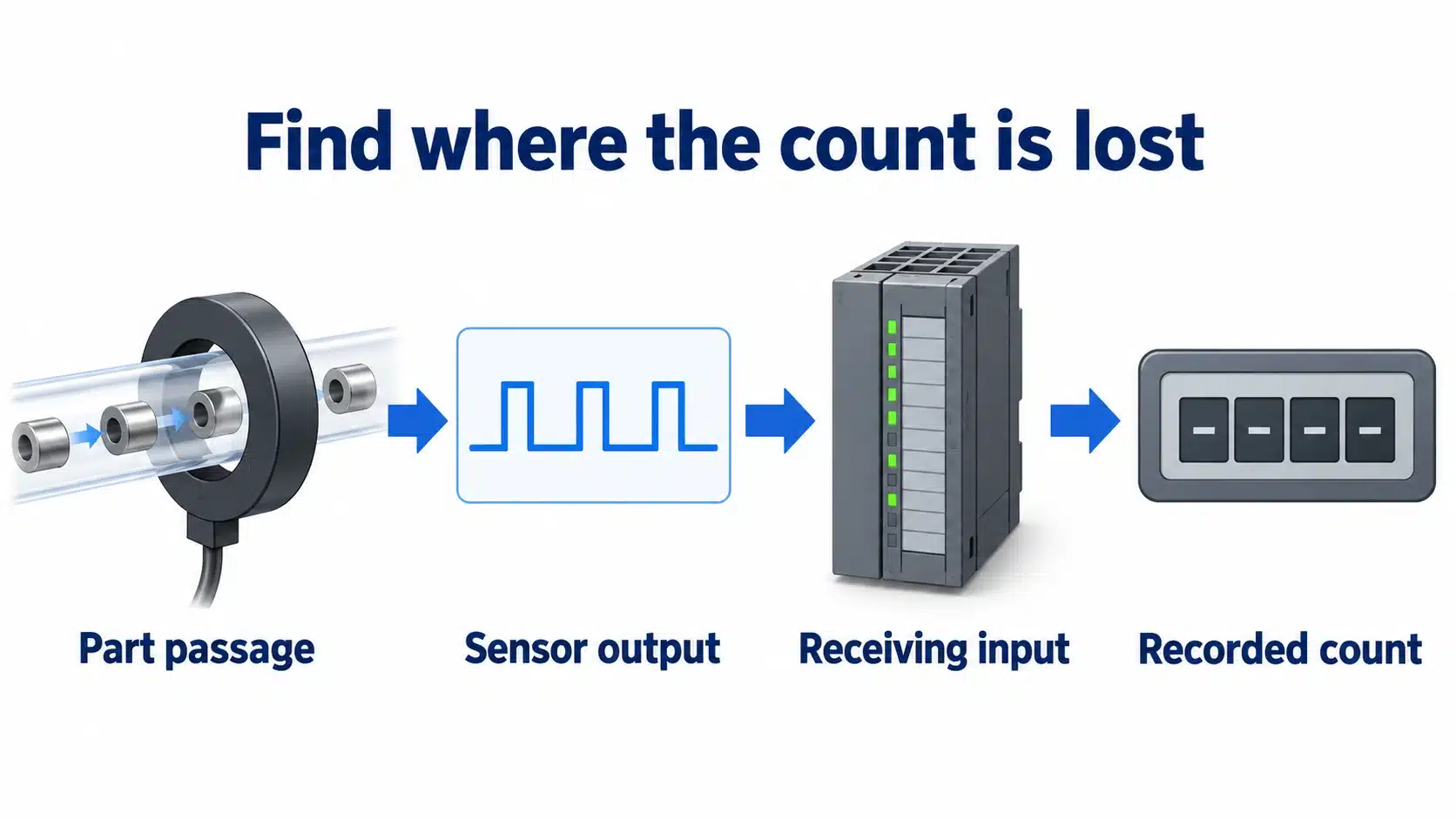
Follow the same events through the system: actual passage, sensor output, signal at the receiving input, and recorded count. At each step, ask whether the evidence has enough time resolution to distinguish consecutive parts.
An indicator light is useful for initial observation, but a visible flash does not establish the electrical pulse width or confirm that the programmable logic controller (PLC) accepted it. Similarly, a slowly refreshed monitoring screen may not show every input transition. Use the model's diagnostic functions or an appropriately connected measurement instrument where the event is too fast to observe reliably.
If passages are confirmed but the sensor output lacks separate events, concentrate on detection and the sensor's output processing. If distinct output events are present at the sensor but not at the receiving terminal, investigate the connection and electrical conditions. If suitable signals reach the input but the count is still wrong, move to input configuration and program logic. This sequence avoids changing a working sensing setup to compensate for a downstream fault.
Check the Target, Feed Path and Ring Installation
Part Material, Size and Position Through the Aperture
The opening tells you whether a part or feed tube can fit through the ring. It does not establish that every fitting object will be detected reliably. A minimum-object specification also needs its test conditions: a reference metal sphere is not automatically equivalent to a thin spring, hollow component or irregular production part.
Compare samples that count reliably with samples associated with a miss. Record material, dimensions, shape and orientation. Then check the permitted path through the installed tube or guide. The useful question is whether the actual part produces a dependable detection event throughout the movement allowed by the machine, rather than whether one convenient hand-held pass can trigger the sensor.
If the problem follows a particular batch or part shape, keep the sensor settings unchanged while comparing those samples under the same conditions. If the problem follows a change in the guide or part path, investigate that change first. Do not assign a universal weak position inside every ring or assume that one material correction applies to all models; establish the limits from the relevant data and representative testing.
Tube, Mounting Metal and Sensitivity Settings
Evaluate the sensor as installed. Record the tube material, wall and outside dimensions, how it is held, and the surrounding brackets or metal components. Check those details against the sensor's installation instructions. Where a model specifies clearance from metal or a particular mounting arrangement, reproduce that arrangement before assessing its detection performance.
Inspect changes since the setup last worked: a replacement tube, a moved bracket, a loose mounting point, accumulated material, or an adjacent device. These are investigation prompts, not proof that every such change causes a miss. Compare the empty path and actual-part response to find out whether the installation remains within the documented conditions.
If sensitivity is adjustable, follow the model's procedure with representative parts in the final installation. Verify both reliable part detection and the expected no-part state. Turning sensitivity to maximum without checking either state does not demonstrate a sound adjustment. A more sensitive setup cannot repair a pulse that the PLC filters out, and it should not be used to conceal an unstable feed path.
Save the original setting before adjustment. If the expected response cannot be obtained within the documented range, retain the observations and seek model-specific guidance instead of assuming that another turn of the adjuster will solve the problem.
Check Detection Mode, Part Spacing and Output Timing
Slow Movement, Stops and Restart
Static and dynamic ring sensors do not necessarily respond to the same event. Static detection can maintain a presence indication for metal in the sensing zone; dynamic detection responds to a passing part. The exact response to very slow motion, a held target and a restart depends on the model and its signal processing.
A stationary sample test therefore needs to match the intended operating principle. Loss of an indication while holding a part inside a dynamic sensor does not, by itself, prove a defect. Conversely, a successful fast pass does not establish what will happen when a feeder pauses with a part already inside the ring.
Reproduce the relevant sequence under controlled conditions: passage, a permitted pause, removal and restart. Observe the sensor output alongside the controller's count-enable and reset conditions. If a part crosses before counting is enabled, a valid detection event can be absent from the recorded batch. Correcting that sequence requires understanding the machine logic, not simply changing the detection mode.
Short Pulses, Long Holds and Closely Spaced Parts
Part spacing and output spacing must be checked separately. The sensor may hold its output after a brief detection event. That can make the signal easier for a receiving input to capture, but the resulting electrical signal is no longer a direct picture of the time the part occupied the sensing region.
For edge-based counting, the receiving system needs a qualifying transition for each intended event. It also needs the signal to recover sufficiently before the next qualifying transition. If an output remains active across several closely spaced passages, a receiver counting the transition into that state cannot obtain a new edge for each passage. Whether events extend a pulse, are ignored during a hold period, or are processed differently must be checked in the exact sensor documentation.
This creates two different investigations. When separate output pulses exist but are too short for the receiving path, a documented pulse extension or a suitable capture method may help. When the output does not return between intended counts, extending the hold further is not the remedy. Investigate part separation, the configured hold behavior and the applicable recovery requirements.
Measure the shortest active and inactive intervals at the receiving input during the tightest allowed production spacing. Compare both with the input's requirements. Do not calculate a guaranteed parts-per-second rate from the reciprocal of one pulse setting, or assume that a sensor's headline switching rate describes the entire installed counting system.

Check the Electrical Signal and PLC Input
Supply, Wiring and Output Compatibility
Confirm the complete sensor order code and the actual input channel before interpreting a voltage measurement. Supply range, connector assignment, output circuit and input reference must match the documented configuration. PNP/NPN describes the electrical output arrangement; normally open/normally closed describes switching logic. Selecting one does not establish the other.
Check the supply at the sensor under the conditions associated with the fault, rather than relying only on the power supply's nominal rating. Inspect connectors and cable condition, and compare the signal at the sensor with the signal reaching the connected input. Use the receiving device's documented reference and thresholds. A measurement made with the load disconnected may not represent the circuit that operates the machine.
When an intermittent fault coincides with movement or another machine action, record that timing and investigate the relevant connection or supply path. Avoid declaring electrical noise to be the cause without observations that distinguish it from an unsuitable pulse or a program reset. Do not copy wire colors or pin assignments from another sensor family, even if the housing looks the same.
If the sensor offers several output functions, verify which function is assigned to the connected channel. A batch-complete or counter-status output is not necessarily an individual-part pulse. Confirm this in the parameter record before comparing its transitions with the number of physical parts.
Input Filters, Scan-Based Counting and High-Speed Inputs
A signal can reach the input terminal and still fail to become a countable event. Input filtering may reject brief states. Scan-based logic may then observe the accepted input only at particular updates. Finally, the counting instruction applies its own enable, edge and reset conditions. Check these stages separately.
Filtering is intended to reject unwanted transitions, but an unsuitable setting can also remove a legitimate short pulse or prevent the intervening state from being recognized. Compare the measured waveform with the actual input specification and configuration. Reducing filtering without checking noise susceptibility can exchange missed counts for false counts; the goal is reliable recognition of both states.
Pulse capture and high-speed counting are also different functions. For example, the documented S7-1200 pulse-catch function operates after the input filter and does not make every pulse within one scan available as a separate read event. That model-specific limit illustrates why enabling a feature named “pulse catch” is not sufficient evidence that every part will be counted.
For a rapid pulse stream, verify whether the selected channel supports an appropriate hardware counter or event-based capture method, and check its documented electrical and timing limits. A high-speed function cannot recover an event that the sensor did not produce or that an earlier input stage rejected. Keep the program's selected edge, count enable, resets and batch window in the same investigation. An input monitor changing state is only one piece of evidence; the final question is whether the intended event increments the correct count once.
Retest Under Production Conditions and Record the Result
Change One Setting at a Time
A useful retest demonstrates why an adjustment worked. If sensitivity, pulse length and input filtering all change together, an improved total does not tell you which condition caused the original error or whether another problem was introduced.
- Save the starting configuration and the observed discrepancy. Record the reference passages, output behavior and controller result within the same counting window.
- Make one justified adjustment within the relevant instructions. State what observation should change if the diagnosis is correct.
- Repeat the same test, comparing event records as well as totals where practical. Check for additional counts as well as missing counts.
- Extend the test to the allowed production variations: representative small or difficult parts, permitted paths, close spacing, speed changes and the relevant stop/start sequence. Check the expected no-part condition too.
- Record the final settings, test conditions and remaining limitations. Select test duration and acceptance criteria for the machine's requirements; a short successful trial is not a general guarantee of error-free production.
If the fault remains unexplained or the system behaves unpredictably, keep the equipment in a safe state and escalate with the collected evidence. Do not compensate for uncertainty by widening the acceptable count discrepancy without an authorized engineering decision.
What to Send for Technical Support
A report that says “the ring sensor sometimes misses” leaves several different faults indistinguishable. Provide enough information to reproduce the conditions and identify the first disagreement in the counting sequence:
- Complete sensor model and parameter settings, including any configured output or timing function.
- Part material, dimensions, shape and representative samples, including those associated with misses.
- Tube or guide details and installation photographs showing nearby metal and the permitted path.
- Operating speed, closest part spacing, stop/start behavior and the circumstances in which the fault appears.
- Supply and wiring information, receiving input model, filter/capture settings, and relevant count-enable or reset behavior.
- Reference passage record, observed output/input signals, final count and the effect of each attempted change.
For an XSZ sensor, include its full order code rather than only the ring aperture. The objective is to decide whether the existing installation and settings can be corrected or whether a different documented configuration needs evaluation. A replacement should address the identified limitation and then pass the same production-condition checks.
Technical Sources
- wenglor — IR2D002 Operating Instructions: model-specific target conditions, installation, sensitivity adjustment and output processing.
- ifm — Smart Inductive Ring Sensors with IO-Link: static and dynamic applications and configurable output functions within the described family.
- Siemens — S7-1200: Configuring Digital Input Filter Times: input filtering and its relationship to supported input functions; V20 documentation, November 2024.
- Siemens — S7-1200: Pulse Catch: pulse capture after filtering and the documented scan-related limitation; V20 documentation, November 2024.