
Proximity Switch Wiring Diagram: Complete Guide to 2-Wire, 3-Wire, 4-Wire, PNP & NPN
Introduction
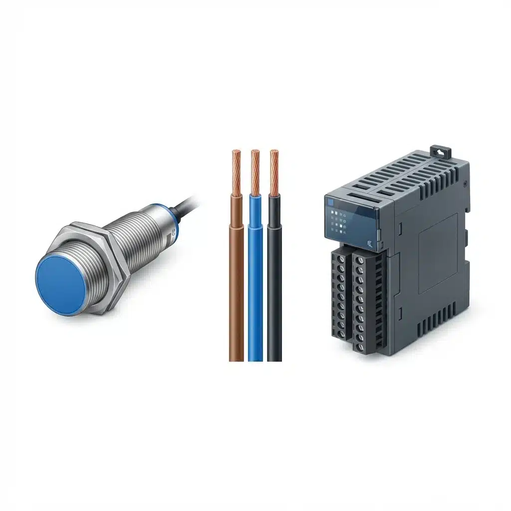
Wiring a conventional DC proximity switch involves three separate decisions. Wire count describes how supply and signal share the conductors. PNP or NPN describes which direction the output moves current when it switches. NO or NC describes whether the output conducts with the target present or with it absent. Each decision must match the receiving circuit on its own terms. Getting one right does not settle the other two.
Mixing these decisions can cause commissioning faults. A sensor can light its detection indicator while the PLC input stays off, because the input has no complete current path. Wiring by cable color alone can put supply voltage on the wrong terminal and damage the sensor or the input card.
This guide covers conventional switching sensors. NAMUR interfaces, IO-Link connections, analog outputs and safety-rated systems each have their own connection instructions and are outside its scope. Isolate power before changing connections, and secure the machine against movement during commissioning. AC circuits must be handled by suitably qualified personnel under the applicable electrical safety procedure.
Quick summary: a two-wire electronic switch sits in series with its load. A three-wire switch has separate supply and output conductors. A four-wire switch usually adds a second output, though some models assign the fourth conductor to another function.
Common DC wire-color reference
| Color | Abbreviation | Usual role in the circuits below | What the color does not tell you |
|---|---|---|---|
| Brown | BN | Positive supply, +V | The permitted supply voltage |
| Blue | BU | Supply return, 0 V | A protective earth or chassis connection |
| Black | BK | Switching output | Whether the output is PNP or NPN, NO or NC |
| White | WH | Second output or a model-defined function | That it is an NC output |
These colors follow the convention shown in manufacturer connection diagrams such as those published by Pepperl+Fuchs. They are a common convention, and the specific device’s diagram still defines each conductor’s function and connector pin assignment. Never infer either from the cable alone.
Understanding Wire Configurations: 2-Wire, 3-Wire, and 4-Wire Proximity Switches
The wire arrangement determines how the sensor powers its electronics. A two-wire series circuit can reuse a two-conductor cable, but its leakage current and ON-state voltage drop must fit the receiving input. Separately powered three-wire sensors avoid relying on that series path for their operating power.
Three factors usually decide the arrangement, in this order:
- The receiving input type and its ON and OFF limits.
- The number of conductors already installed.
- Whether the control logic has a real use for a second output.
For conventional DC switching with a known input module, prioritize the receiving circuit before cable convenience. The appropriate choice changes when the existing conductors or required output functions change.
2-Wire Proximity Switch Wiring Diagram
A two-wire electronic proximity switch shares one series path with its load. A mechanical contact needs no power of its own, but an electronic sensor does, and in a two-wire circuit it must take that power through the load.
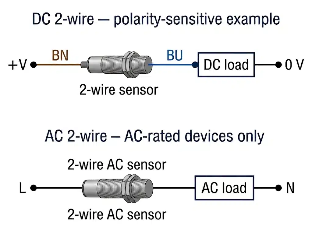
These diagrams show circuit principles. They are not universal terminal assignments. Some DC two-wire sensors are polarity-sensitive and others are not, so the model’s diagram decides. An AC rating does not by itself permit DC operation. An ordinary series-connected two-wire sensor must never be connected directly across the supply without its required load, because omitting the required load can overload or damage the circuit; internal protection must not be assumed.
Taking power through the load creates two separate constraints. When the output is OFF, the sensor still draws a small leakage current to keep its electronics running. That current flows through the load and can hold a sensitive PLC input on. When the output is ON, the sensor keeps a residual voltage across itself for the same reason, so the load receives less than the full supply voltage. OMRON’s proximity-sensor guidance treats these as two distinct checks. The input must reset reliably in the OFF state and operate reliably in the ON state.
Two-wire is a reasonable first candidate when replacing a sensor on an existing two-conductor cable. Compare the sensor’s leakage current, minimum load current and ON-state voltage drop with the receiving device’s OFF and ON requirements. If the ranges do not overlap, the circuit will not work reliably, however convenient the wiring. A three-wire sensor or a suitable interface is then the better choice.
3-Wire Proximity Switch Wiring Diagram
A three-wire sensor separates supply from signal. Brown and blue power the electronics continuously, and black carries the switching output to the receiving circuit.
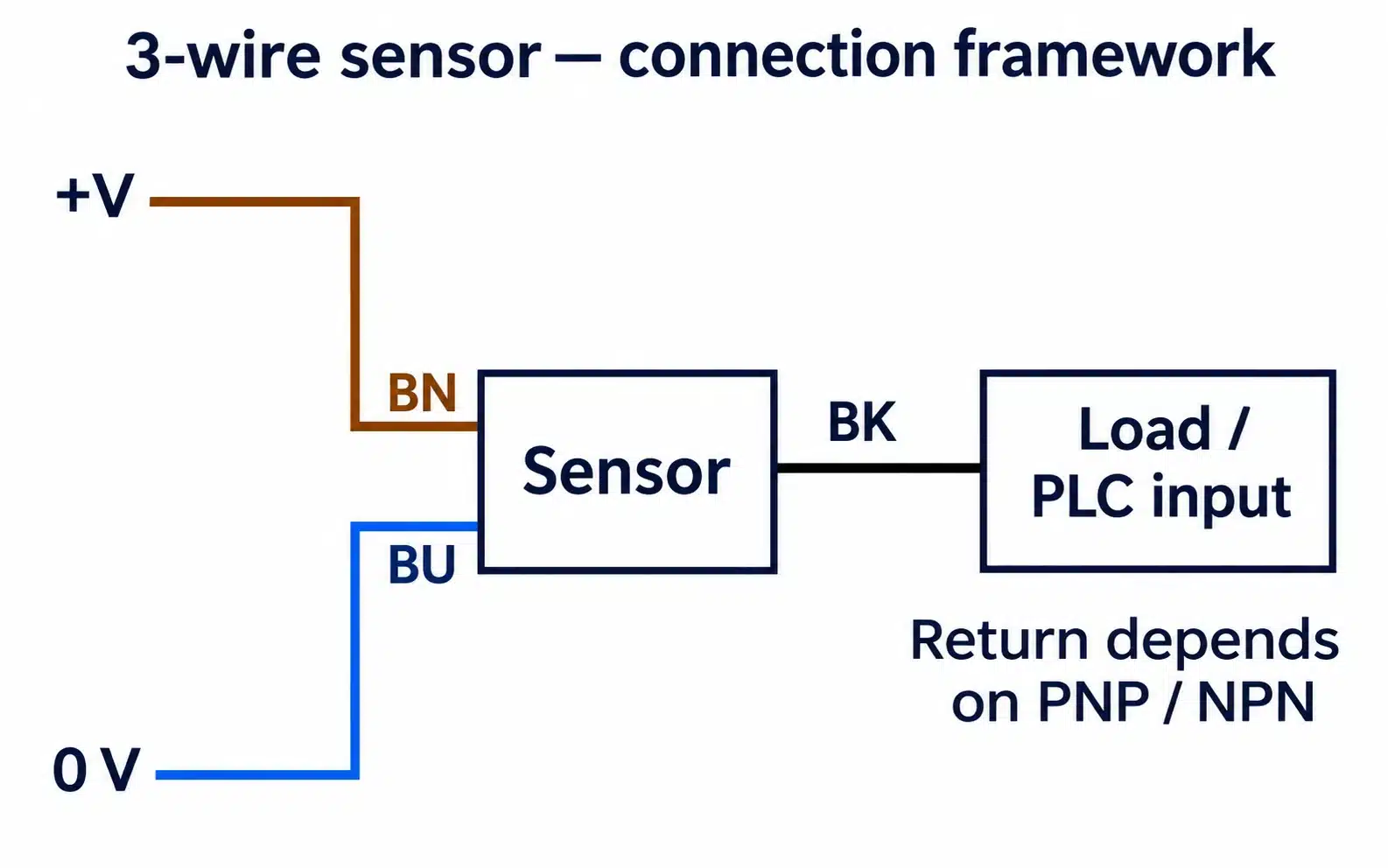
The diagram leaves the load return open on purpose. Where that return connects is exactly what distinguishes PNP from NPN, covered in the next section.
Because the electronics draw power from their own conductors, the load circuit no longer has to carry the sensor’s operating current. For that reason, a three-wire sensor is a sound starting point for a new DC PLC installation when the input type is known. The output still has a voltage drop, and cable routing still matters. For example, the ifm IFS268 datasheet specifies a maximum switching-output voltage drop of 2.5 V for that PNP NO model. The figure applies only to that model, but it shows why a three-wire output should not be treated as a direct connection to the supply rail.
4-Wire Proximity Switch Wiring Diagram
A common four-wire arrangement adds a second switching output to the three-wire layout. On a complementary version, one output conducts when the target is present and the other conducts when it is absent.
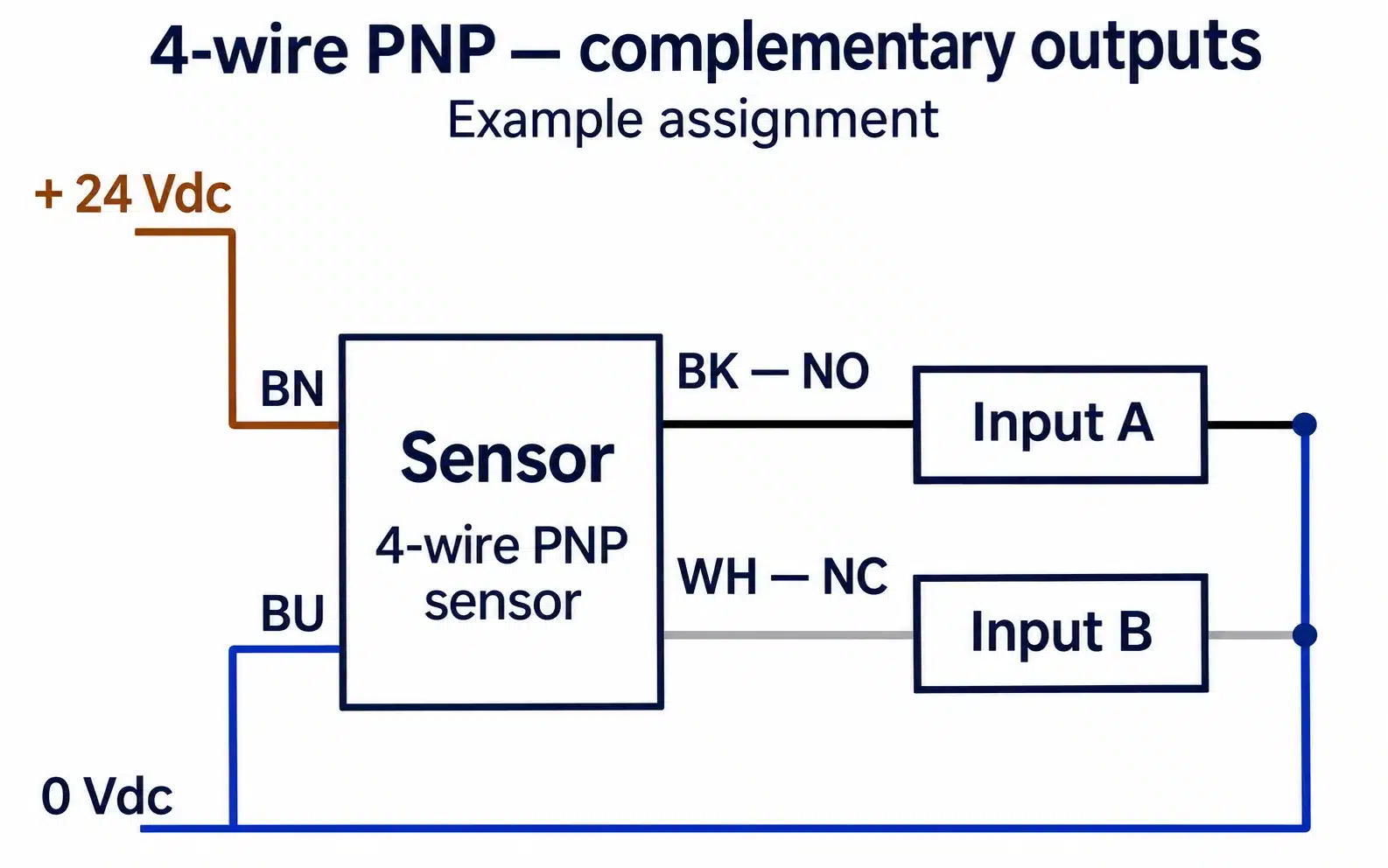
Use this example only when the selected device’s documentation confirms black as NO and white as NC. Pepperl+Fuchs publishes complementary four-wire configurations in both PNP and NPN versions. In the NPN version, each load connects between +V and its output. Keep the two outputs separate, and insulate an unused conductor individually as the manufacturer instructs.
If a model’s diagram assigns the fourth conductor to a teach-in or programming input, treat it as an input and do not wire it as a second load output. Wire count alone does not tell you which arrangement a model uses.
Complementary outputs let a PLC check that the two signals stay opposite, which can reveal some wiring faults. Both signals still come from one sensor, so they are not independent safety channels. An ordinary non-safety-rated proximity sensor does not become a personnel-protection interlock merely by using NO and NC outputs. OMRON explicitly excludes its general proximity products from use as safety devices intended to protect human life. That duty requires a properly specified safety system.
PNP vs. NPN Proximity Switch Wiring: What’s the Difference?
The reliable way to choose between PNP and NPN is to trace conventional current from supply positive, through the sensor output and the receiving input, back to supply negative. The circuit works only if that whole route exists. PLC brand and the country where the machine was built do not establish the input circuit.
PNP Wiring Diagram (Sourcing Output)
A PNP output supplies current to the load when it is ON. The load connects between the output and 0 V. In a matching PLC input circuit, the input group’s common terminal connects to 0 V.
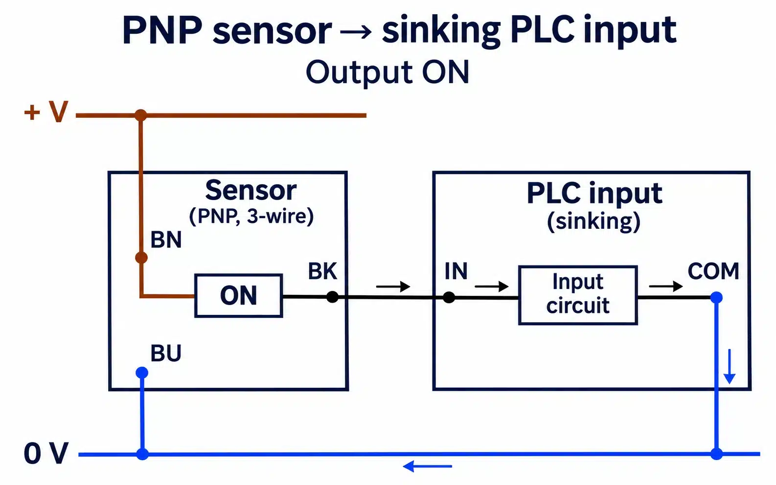
With a nominal 24 V supply, an ON PNP output sits close to +24 V measured against 0 V, minus the output drop and any wiring drop. The PLC input must still receive enough voltage and current to cross its ON threshold. A PNP NO sensor reaches this state when the target is detected. A PNP NC sensor reaches it when no target is detected.
NPN Wiring Diagram (Sinking Output)
An NPN output provides the return path to 0 V when it is ON. The load connects between +V and the output. A matching PLC input pushes current from its positive common, through the input circuit, into the sensor.
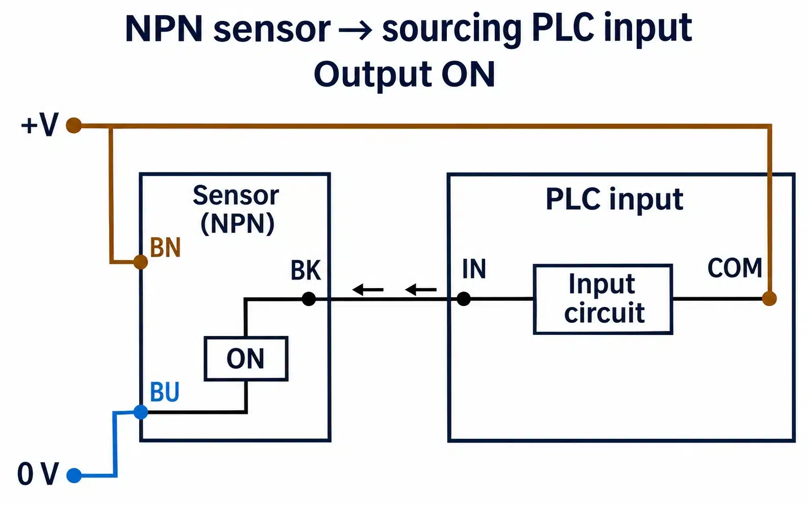
An ON NPN output sits close to 0 V measured against the supply return, apart from a small output drop. A low voltage on the signal wire can therefore mean the PLC input is energized. Assuming that a high voltage means ON will mislead troubleshooting unless the output and input types are already identified.
In both circuits, brown goes to positive and blue to the return. Changing from PNP to NPN never means reversing the power wires.
Quick Comparison Table: PNP vs. NPN
| Criterion | PNP | NPN |
|---|---|---|
| Output action when ON | Sources current | Sinks current |
| Load connection | Output to 0 V | +V to output |
| Output voltage when ON, measured to 0 V | Near +V | Near 0 V |
| Compatible PLC input | Sinking input | Sourcing input |
| Usual input-group common | 0 V | +V |
| NO or NC available | Either, depending on model | Either, depending on model |
AutomationDirect’s sensor guidance confirms the pairing: a sourcing sensor needs a sinking input, and a sinking sensor needs a sourcing input. Base the choice on the actual input module and how its common is wired. The same PLC brand may offer several input circuits, and some modules accept either polarity, configured per group.
Normally Open (NO) vs. Normally Closed (NC) Output Logic
NO and NC describe when the output conducts relative to the target. PNP and NPN describe which current path it conducts through. Any combination of the two is possible, depending on the model.
| Target condition, with the sensor powered and operating normally | NO output | NC output |
|---|---|---|
| Target absent | OFF | ON |
| Target detected | ON | OFF |
For these electronic sensors, ON means the semiconductor output is conducting. There is no mechanical contact inside the housing.
NC logic can make a lost signal noticeable when the application expects the input to stay energized. The drawback is that a detected target, a lost supply and a broken conductor can then all look the same to the PLC: the input drops out. A short circuit or an internal sensor failure may behave differently again. The useful design question is what the controller does when the expected signal disappears, and how it tells a process event from a fault. Choosing NC does not, by itself, provide fault detection or any safety rating.
How to Wire a Proximity Switch to a PLC
Start with the input module’s connection diagram rather than the sensor’s. AutomationDirect’s Productivity1000 hardware manual shows both current paths and explains why channels that share a common cannot always mix sensor types freely.
- Identify both devices before stripping any wire. Record the sensor’s full part number, supply type and range, output type, NO/NC function and connection diagram. Identify the PLC input group, its common terminal and its permitted input voltage. If the sensor cannot be identified, stop before applying power.
- Match the current path. Use a PNP sensor with a sinking input, or an NPN sensor with a sourcing input. Trace the route from +V through the active output and the receiving input back to 0 V. Follow the module’s instructions for common terminals, especially on grouped or isolated inputs.
- Check the electrical margins. The sensor’s output capacity must cover the input current. Under load, the ON-state voltage must meet the PLC’s ON threshold, and OFF-state leakage must stay below its OFF limit. Include cable voltage drop and any minimum-load requirement from the sensor manufacturer.
- Connect with power isolated. Wire the supply, the output and the input common according to the confirmed circuit. Check for loose strands and accidental bridges. Do not tie unused outputs to a supply rail to keep them tidy.
- Verify the whole chain before enabling motion. Restore power under the commissioning procedure. Move a suitable target in and out of range, and compare three things: the sensor indicator, the PLC channel indicator and the input bit in the program. Both target states must match the intended NO/NC logic. If the sensor indicator changes but the PLC bit does not, investigate the interface before adjusting the sensing distance.
Hypothetical example: an existing DC input group returns its common to 0 V, and its specification calls for a sourcing sensor. A three-wire PNP sensor is the direct electrical match. An NPN sensor in the same housing with the same sensing distance is not a like-for-like substitute, because its output cannot supply the current that group needs. Keeping the PNP interface avoids an extra conversion component. Sensing distance, environment and installed operation still need to be confirmed separately.
If the sensor and the input are incompatible, first look for the correct sensor version or a configurable input group that accepts it. Otherwise, use a suitable signal converter. An interposing relay works only when its coil current, the sensor’s output protection, the relay’s contact rating and its switching speed all suit the application. Pull-up and pull-down resistors are circuit designs, and they do not convert polarity in general. They can invert the logic, add leakage or draw current from the output. Base any resistor interface on a documented calculation and test both states, rather than trying a value that happens to be on hand.
Common Wiring Mistakes & Troubleshooting Checklist
Before replacing a sensor, establish which part of the chain fails. Start by distinguishing a loss of power, a missing sensing transition and a transition that fails to reach the PLC.
| Observation | Plausible cause | Distinguishing check and next action |
|---|---|---|
| No power indicator, or the supply collapses | Reversed polarity, a short, wrong supply voltage or damaged wiring | Isolate power and compare the connections with the exact diagram. Then measure supply voltage at the sensor with the circuit safely energized for measurement. Do not assume the sensor has reverse-polarity protection. |
| Sensor indicator changes but the input stays OFF | Wrong common, PNP/NPN mismatch, broken signal conductor or insufficient ON voltage | Measure the output against the correct reference with its intended load connected, then compare the PLC terminal with the sensor output. |
| Two-wire input stays ON when the specified logic should be OFF | Leakage current exceeds the input’s OFF tolerance | Check the OFF-state input voltage or current against both specifications. Use a compatible interface or a bleeder arrangement approved by the sensor manufacturer. |
| Errors coincide with relay or valve switching | Inductive surge or supply disturbance | Inspect surge suppression and supply behavior, correct the affected load circuit, then repeat the switching tests. |
| Instability starts after neighboring sensors are installed | Overlapping sensing fields or mounting effects | Test one sensor at a time and compare the spacing with the model’s mounting requirements. Shielded cable will not fix overlapping sensing fields. |
OMRON’s proximity-sensor precautions describe a bleeder resistor as a way to bypass leakage current. It gives that current a second path, lowering the voltage left across the receiving input in the OFF state. Its resistance and power rating must bring the input below its OFF threshold without overloading the sensor or overheating when the output is ON. No single resistor value is safe for every two-wire proximity sensor.
For a compatible DC relay coil, a flyback diode connects in parallel with the coil and is reverse-biased during normal operation. In the NPN example below, the cathode goes to the positive side and the anode to the switched side.
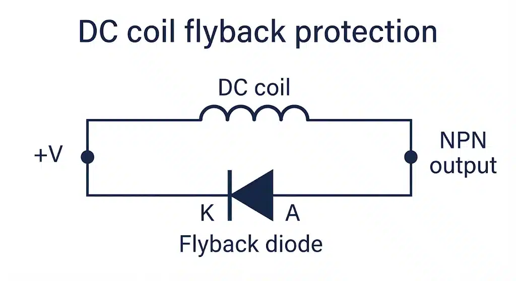
When the output switches off, the coil’s stored energy circulates through the diode instead of forcing a high voltage across the sensor output. OMRON’s relay and solid-state relay guidance treats DC diode suppression separately from AC methods, so never fit this simple diode across an AC coil. The suppressor must suit the actual coil and output ratings. A diode also slows the relay’s release, so check the effect on machine timing as well as on output survival.
Route signal wiring away from noisy power conductors according to the equipment’s installation instructions. Keep two uses of “shielded” apart. A shielded sensor housing shapes the sensing field and sets the mounting conditions. A shielded cable reduces electrical interference on the signal. They address different problems.
Frequently Asked Questions (FAQ)
Can I replace a 2-wire proximity switch with a 3-wire one?
Often, yes, but you cannot simply connect two of its wires and leave the third unused. A three-wire sensor needs separate supply and signal paths. Check that enough conductors are available, that the supply suits the new sensor, and that the receiving input matches its PNP or NPN output. Replacing an AC two-wire circuit may also require a DC supply and a suitable interface. Decide from the complete circuit rather than from a matching housing diameter.
What happens if you wire a PNP sensor as an NPN?
The input may fail to energize because the intended current path is incomplete. Some incorrect connections can also short an active output to the opposite rail or exceed a device rating. Swapping brown and blue does not convert the sensor. Isolate power, identify the sensor output and PLC input types, then rewire correctly or fit an appropriate interface.
How do I test a proximity switch with a multimeter?
These steps apply only to a known, conventional low-voltage DC switching sensor. First secure the machine against movement, and confirm the rated supply, output type and wire functions. Use a meter and leads rated for the circuit.
- With power isolated, connect the sensor to a compatible input or to a known load within its ratings. An unloaded electronic output can give misleading voltage readings.
- Select DC volts before restoring power for the test, then measure the supply between brown and blue.
- Measure black against blue while moving the correct target in and out of range. With a suitable load, a PNP output approaches the positive rail when ON, and an NPN output approaches 0 V when ON. Use the NO/NC function to decide which target state should produce ON.
- Compare both readings with the sensor and input specifications. If switching appears at the sensor but not at the PLC terminal, investigate the connecting circuit. If neither changes, check the target and the sensor setup before concluding that the output has failed.
Never use resistance or continuity mode on an energized circuit. Fluke’s guidance requires power to be removed before continuity testing. Continuity mode can check an isolated conductor, but it cannot test a powered semiconductor output. These steps are not a safe way to identify an unknown sensor, and they do not apply to live AC mains testing.
What is the maximum cable length for a proximity sensor?
No single limit applies to all proximity sensors. The allowable length depends on the selected device’s cable specification and on the installed circuit. Voltage drop, signal timing, cable capacitance and interference can each become the limit well before the cable becomes physically impractical.
Use the cable manufacturer’s conductor resistance to estimate the drop in each current-carrying path, then check the worst-case supply and signal margins at the far end under load. Resistive drop increases with both length and current. Follow the device instructions on cable type, routing and shield termination, and remember that a shield does not recover lost voltage. After extending a cable, repeat the two-state input checks and the switching tests at the required operating rate.
Conclusion
Make the electrical decisions in this order: supply type and voltage range, then output current path (PNP or NPN), then target logic (NO or NC). Next, confirm that the wire count, load requirements and PLC common support the resulting circuit. A matching connector and a lit sensor indicator are only partial evidence. The wiring is correct when the right PLC input changes reliably in both target states.
For a new DC PLC installation, a compatible three-wire sensor is the practical starting point. Keep a two-wire sensor when its leakage and voltage-drop limits fit the existing input. Choose four-wire when the additional, documented output serves a real control purpose.
XSZ’s inductive proximity sensors and capacitive proximity sensors are available to browse by category. For a replacement inquiry, send the full code of the existing sensor, the supply specification and the PLC input wiring diagram through the site’s inquiry route. With that information, the electrical interface can be reviewed together with the sensing requirement.
Technical References
- Pepperl+Fuchs: Sensor Connections and Sensor Outputs, Sensors and Systems catalog, 2012. Series two-wire, three-wire and complementary-output principles. Historical technical reference, not current product availability.
- Pepperl+Fuchs: F1 series four-wire connection examples, 2012. Conductor colors and model-specific PNP/NPN NO/NC arrangements.
- OMRON: Proximity Sensors, Further Information. Leakage current and residual voltage.
- ifm: IFS268 datasheet, revision IFS268-02. Model-specific PNP NO output and switching-voltage drop.
- AutomationDirect: Sensors Frequently Asked Questions. Sourcing and sinking sensor and input pairing.
- AutomationDirect: Productivity1000 Hardware Manual, Chapter 5. Input circuits, common terminals and interface considerations.
- OMRON: Proximity Sensors, Explanation of Terms. NO/NC output behavior and shielded/unshielded sensing construction.
- OMRON: Proximity Sensor Safety Precautions. Safety scope, two-wire load compatibility, mutual interference and installation precautions.
- OMRON: Surge Suppressor Selection, FAQ02804. DC and AC suppression choices and their effect on operation.
- OMRON: Solid-state Relays, Further Information. DC inductive-load suppression principles.
- Fluke: What Is Continuity?. Safe use of the continuity function.