
Proximity Sensor Symbols: Types, Meanings, and Wiring Diagrams
Start by finding the sensing label, NO/NC function, output type, and supply/output connections. Read them separately: NO/NC tells you when the output is active; PNP/NPN tells you how it drives the load. Then follow the signal to the PLC input. A contact-shaped PLC instruction tests a data bit, not the sensor's physical contact.

Quick Reference: What Does a Proximity Sensor Symbol Tell You?
Find the nearest device label and follow its lines before interpreting an isolated shape. The examples below are reading cues, not a library of standardized IEC symbols.
| Example mark or label | Read it as | What to follow next |
|---|---|---|
| Inductive | The sensing principle: a suitable conductive metal target affects the sensing circuit | Locate the sensing face and the target's path |
| NO or NC | The target condition that makes the output active | Compare target-absent and target-detected states |
| PNP or NPN | The electronic output type, separate from NO/NC | Trace OUT through the load toward 0 V for PNP, or from +V through the load to OUT for NPN, in the three-wire DC examples |
| +V, 0 V, OUT | Supply, return, and switching-output functions in the teaching drawings | Follow OUT to the receiving input and identify that circuit's supply reference |
| Contact-like mark labeled XIC in the Rockwell example | A software test of the addressed data bit | Match the input channel to the tag being tested; the icon alone does not tell you the sensor's NO/NC function |
The practical distinction is between function, connection, and logic. Finding one of them does not automatically identify the other two.
Use one hypothetical example throughout this guide: a three-wire DC inductive sensor labeled PNP, NO, with a steel bracket moving toward and away from its sensing face. Assume normal powered operation and a target that meets the sensor's detection conditions. This is a teaching example, not an XSZ model or a ready-to-wire circuit.
Read the label first. Inductive identifies the detection principle. NO means the output is off with the bracket absent and active when it is detected. PNP means the active load path runs from +V through the output stage and OUT, then through a compatible load to 0 V. On the drawing, identify those three functions before looking for connector numbers. The later sections explain each step and finish by matching the drawing to the actual device.
How to Read a Proximity Sensor Symbol on a Drawing
Identify the Device Boundary, Sensing Function, and Output
Find the sensor's device designation in the drawing and locate its entry in the legend or device list. Trace the boundary around that device, then mark the lines used for supply, return, and output. In the PNP NO example, this is where you distinguish the two power connections from OUT.
An electronic sensor can contain a detector, signal processing, and an output transistor. A small contact-like representation may describe the switching function without showing that internal circuit. Read it alongside the terminal and output information rather than treating it as proof of a potential-free mechanical contact.
The following original teaching representation separates those roles; it is a functional explanation, not a standardized IEC symbol:
Target → Sensing function → Output stage → OUT
Supply connections: +V and 0 V; output description: PNP or NPN; switching function: NO or NC.
If the drawing groups “inductive / PNP / NO” beside one device, enter those as three separate observations. You have identified the detection method, output circuit, and target/output relationship; you have not yet identified the connector pins.

Read the Drawing Legend Before Assuming a Symbol Convention
A machine overview may show only the sensing function; a connection drawing may show terminals and the output circuit. Use the legend for that drawing to decide which level you are reading. If a coil-like or contact-like mark is unexplained, record it as unknown rather than assigning a sensor type from its shape.
IEC 60617 is the graphical-symbol database for electrotechnical diagrams. Its public catalogue establishes the database's scope, not the identity of a particular mark in your drawing. The original functional illustrations here help explain relationships; they are not reproduced IEC symbols.
How Symbols Distinguish Different Sensing Principles
Inductive and Capacitive Proximity Sensors
An inductive sensor detects an appropriate conductive target through the effect of the target on its alternating magnetic field. A capacitive sensor detects a change in capacitance. These mechanisms explain why the sensing function matters independently of the electrical output: a similar output arrangement can serve different detection principles.
Read the sensing label alongside the device description. An electrical component drawn inside a circuit does not, by itself, identify the sensing principle of the complete device.
For the steel-bracket example, the inductive label explains why the metal target can be detected without touching the sensing face. The three-wire description tells you to look for separate supply, return, and output lines. You still need the PNP label or circuit to determine how the load is connected.
Magnetic Sensors, Reed Contacts, and Related Non-Contact Devices
In the reed-switch example, an approaching magnet acts on physical contacts inside the device. That differs from the electronic output stage in the PNP NO example. Other magnetic sensors use electronic outputs, so a magnetic sensing label alone does not identify the contact or transistor arrangement.
When a drawing shows a magnetic sensing function, determine whether the specified device uses contacts or an electronic output. That difference changes what its connections mean. “Detects a magnet” describes the sensing task; it does not completely describe the load circuit.
Photoelectric and ultrasonic devices may also appear among a machine's non-contact detectors. Keep their detection labels distinct from their output descriptions. The drawing legend and device identity remain the reference, rather than a universal symbol guessed from the broad word “proximity.”

What Do NO and NC Mean for a Proximity Sensor?
Compare Target-Absent and Target-Present Output States
In normal powered operation, an NO transistor output is on when the target is detected; an NC output is on when it is absent. Apply this to the steel bracket in the example:
| Sensing condition | NO output | NC output |
|---|---|---|
| Target absent | Off | On |
| Target present within the applicable sensing conditions | On | Off |
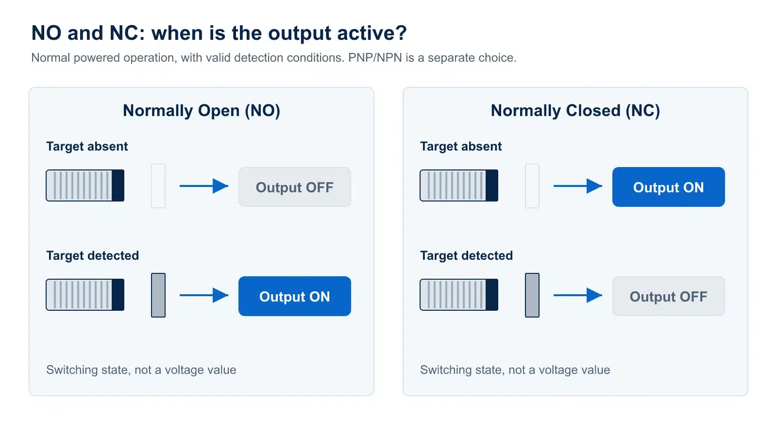
Here, “on” describes the output's active switching state. It does not specify a numerical output voltage or establish that the receiving controller has recognized the signal. Those depend on the output circuit, load, and input requirements.
Use the table with the model's documented operating mode, especially if switching behavior is selectable. It describes normal operation, not what every device does during startup, power loss, a broken wire, or an internal fault. An NC label alone is not evidence that a sensor or the complete circuit has an approved safety function.
Keep Switching Function Separate from PNP or NPN
NO/NC answers when the output is active. PNP/NPN answers how the active output forms a circuit with the load. In the three-wire DC examples, a PNP sensor can be NO or NC, and so can an NPN sensor.
This distinction prevents a common replacement error. Matching “NO” between two labels does not establish that the output can operate the same controller input. Read the output type and switching function as separate fields, then compare the connections.
How to Read PNP and NPN Sensor Wiring Diagrams
PNP: Follow the Output-to-Load-to-0 V Path
In the simplified three-wire DC arrangement below, the sensor has separate +V and 0 V supply connections. Its PNP output supplies the load from the positive side when active:
Active PNP load path: +V → PNP output stage → OUT → Load → 0 V.
Follow the arrows as conventional load current when the output is active. The sensor's own circuitry also needs supply power; it is separate from the load path written above. The functional diagram shows the operating principle. Use the wiring diagram for your sensor model before connecting it.
On the PNP drawing, find OUT and follow it to the load. If that load is a PLC input, continue through the receiving circuit to its 0 V reference. You should be able to trace one complete active load path; an input label without its circuit leaves that part unresolved.
NPN: Follow the Positive-Supply-to-Load-to-Output Path
For the corresponding NPN example, the active output completes the load circuit toward the negative supply:
Active NPN load path: +V → Load → OUT → NPN output stage → 0 V.
The load is now on the positive side of the switching path. That is the difference to follow on the drawing: changing the sensor label from PNP to NPN does not make an incompatible input circuit work.
Compare the two drawings at the load, not just at the letters PNP and NPN. In the NPN version, +V reaches the load first, then OUT completes the active path through the sensor to 0 V. If both versions are NO, the bracket can produce the same absent/present output sequence while still requiring different receiving circuits. The pre-wiring checklist below covers the ratings and terminal details needed to turn this reading into a real connection.

What Changes in Two-Wire, Three-Wire, and Four-Wire Diagrams?
Separate Power Connections from the Switching Load
In a two-wire DC electronic sensor arrangement, the sensor operates in series with the load. It therefore needs to be read differently from a three-wire diagram with separate power connections and an output lead. The historical Pepperl+Fuchs connection guide illustrates both arrangements and explains why an electronic two-wire circuit can have off-state leakage and on-state voltage drop.
Those characteristics matter when the receiving input decides whether a state is on or off. A two-wire electronic device should not automatically be treated as a dry contact simply because only two conductors are drawn.
A four-wire drawing can provide additional output connections. For example, the same manufacturer's guide shows versions with complementary NO and NC outputs. Other arrangements also exist, so count the conductors only as a starting observation. Identify what each terminal actually does before deciding whether two outputs, a combined function, or another interface is involved.
Check Connector Pin Assignments and NAMUR Interfaces
A connection drawing must identify its connector view. Device-side and mating-connector views can be read from different directions, so establish the stated view before mapping +V, 0 V, and OUT to terminal numbers.
Do not assign functions from cable color or connector size alone. De-energize the circuit before changing wiring and follow the machine's applicable isolation procedures; the illustrations in this guide are not a safe-work procedure.
NAMUR is a separate interface case. The public scope of IEC 60947-5-6 describes proximity sensors connected by two wires to a switching amplifier. Do not substitute the generic PNP/NPN path above for that sensor-and-amplifier arrangement. Use the documentation for both sides of the interface, including any requirements of the actual installation.

Why a PLC Ladder Contact Is Not the Physical Sensor Symbol
Trace the Field Output to the PLC Input Bit
Follow the representation through three distinct stages:
Sensor output → Receiving input circuit and channel → Input data used by the program.
The wiring drawing describes the physical circuit. The controller's channel mapping identifies the program data associated with that input. The program then evaluates that data using an instruction.
If the drawing shows a sensor output on one channel but the program tests a different tag, the two representations are not describing the same signal. First establish that relationship; changing an instruction because its icon looks unfamiliar would skip the more basic question of which data it is evaluating.
Read the Logic Instruction Separately from the Sensor’s NO/NC Function
Rockwell's Studio 5000 documentation describes XIC, Examine if Closed, as an instruction that examines a data bit. With the incoming rung condition true, a true bit makes its outgoing condition true; a false bit makes it false.
The contact-like appearance does not establish that the field sensor is physically a normally open contact. A documented NC electronic sensor can provide the input data being examined; the program's interpretation still depends on the bit's state and intended machine logic.
XIC is the Rockwell instruction used in this example. On another PLC platform, use its own instruction definition. Read the hardware output and the software test separately before deciding what the machine logic means.

How to Check a Sensor Symbol Against the Actual Device
Work Through a Labeled Three-Wire DC Example
Return to the hypothetical three-wire DC, inductive, PNP NO sensor introduced at the start. Complete these observations on your own drawing rather than reading the label as one combined symbol:
- Label and device: find the device designation and write down inductive, PNP, and NO as separate fields. Match the label to the device list.
- Target and output: write “bracket absent: output off” and “bracket detected: output active.” Use normal powered operation and valid detection conditions; off does not mean the transistor actively drives the opposite voltage.
- Supply and load: identify +V, 0 V, and OUT by function. Follow +V through the PNP stage, OUT, and the receiving load back to 0 V. Then use the exact connection drawing to assign terminals.
- Channel and program: follow the receiving channel to its input tag. Assuming that tag directly represents the recognized channel state, an active input makes the bit true. In the Rockwell XIC example, a true bit passes a true incoming rung condition; a false bit makes the outgoing condition false.
You should now have a device identity, two expected output states, a complete load path, and a channel-to-tag relationship. A missing item tells you which part of the drawing you have not resolved. This is a reading exercise, not an XSZ model or an instruction to energize an unidentified circuit.

Resolve Missing Model, Terminal, and Input Information Before Wiring
Before making or changing a connection, collect the information in one place:
- Device identity: complete model and suffix, applicable drawing revision, sensing type, and selected NO/NC mode. If the label and drawing disagree, resolve that difference first.
- Supply and load ratings: documented supply range, sensor current demand, output current rating, voltage drop, and off-state leakage, compared with the intended load and input thresholds.
- Terminal mapping: supply, return, and each output, using the stated device-side or mating-connector view. Do not fill missing assignments from a familiar color or housing size.
- Receiving interface: compatible input circuit and common/reference connection; for NAMUR, the appropriate sensor-and-switching-amplifier pair.
- Expected result: target-absent and target-detected states at the output, receiving channel, and program tag, with startup or fault behavior treated separately from normal NO/NC operation.
If a sensing mark is unclear, request its legend. If a terminal is unclear, request the exact connection drawing and connector view. If the input relationship is unclear, request the receiving circuit and channel-to-tag mapping. Each request should fill a specific blank in your reading record.
Once the records agree, an authorized commissioning check can compare the expected and observed states. If they differ, locate the first disagreement between sensor output, receiving channel, and program data before choosing what to investigate. Keep any unresolved terminal or interface requirement open until it is answered.
For a metal-detection application, the XSZ inductive proximity sensor range is a starting point for product information. Send the complete model or label, the drawing you are trying to read, and the intended controller input so the discussion starts with the actual detection point.
Technical References
- IEC — IEC 60617 Graphical Symbols for Diagrams: database scope; not an individually verified symbol drawing.
- Schneider Electric — PNP and NPN in Three-Wire Sensor Connections: solid-state outputs and the distinction between output type and NO/NC function.
- Schneider Electric — PNP and NPN Output Connections: three-wire DC output and load arrangements.
- OMRON — Proximity Sensor FAQ00391: NO/NC target and output states.
- OMRON — Proximity Sensors Technical Guide, Operating Principles: inductive, capacitive, and magnetic detection principles.
- OMRON — GLS Proximity Sensor FAQ00345: the reed-contact and magnet example.
- Pepperl+Fuchs — Sensors and Systems, Sensor Connections/Sensor Outputs: connection examples, issue dated 16 August 2012; not a current specification for every sensor.
- IEC — IEC 60947-5-6:1999: scope of the proximity-sensor and switching-amplifier DC interface.
- Rockwell Automation — Examine if Closed, Studio 5000 Logix Designer 37-00: XIC bit-test behavior and execution conditions.