

What Is an NPN Sensor?
An NPN sensor is a sensor with an NPN transistor switching output. In a typical three-wire DC circuit, the output does not supply positive voltage to the external load. When it turns ON, current can flow from a positively supplied load or input into the sensor output and onward to 0 V. That is what sinking output means.
NPN describes the electrical output, not how the sensor detects a target. An inductive, capacitive or photoelectric sensor can have an NPN output. It also does not tell you whether that output is normally open (NO) or normally closed (NC).
The NPN transistor closes a path toward 0 V when ON.
Current enters the output from a compatible load or input.
Connection to a suitable DC controller input circuit.
How Does an NPN Sensor Work?
Think of the output as a switch on the 0 V side of an external input or load. When the transistor turns ON, the path closes and current flows from +V through that input or load into the output, then through the sensor toward 0 V. This is low-side switching, and the sensor is said to sink current.
For a typical three-wire NPN normally open (NO) sensor, no target leaves the output transistor OFF; detecting the specified target turns it ON. An ON output is pulled toward 0 V under load, but its residual voltage need not be exactly zero. In a typical open-collector circuit, the OFF output is open or high impedance; its measured voltage depends on the connected input or pull-up and is not automatically +24 V.
NPN Output Operation — ON State
Swipe to read the diagram →
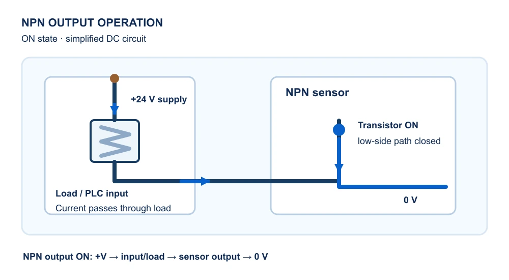
Typical NPN NO output state
| Target condition | Output transistor | Current path |
|---|---|---|
| No target | OFF | No intentional sinking path; the external input circuit determines the output-node voltage. |
| Specified target detected | ON | Current can pass from +V through the compatible input or load to the sensor output and 0 V. |
How to Wire an NPN Sensor to a PLC
The diagram is an illustrative three-wire DC NPN connection to a compatible PLC input that provides current to the sensor output. Brown (BN) powers the sensor from +V, blue (BU) returns it to 0 V, and black (BK) carries the switched output to a digital input. The exact wire or pin assignment must come from the sensor datasheet.
In the circuit shown, the PLC input group's COM+ is tied to +V. When the NPN output turns ON, current flows from COM+ through the input circuit to the black output and returns through the sensor to 0 V. Other modules may name or arrange the common differently; follow the PLC module's own diagram rather than assuming that every input marked “COM” connects to +V.
Swipe to read the diagram →

| Wire | Connection in this example | Function |
|---|---|---|
| Brown (BN) | +V DC | Sensor power + |
| Black (BK) | PLC digital input | NPN output signal |
| Blue (BU) | 0 V DC | Sensor power − |
NPN vs PNP Sensors
Both terms describe the transistor output, not the sensing method. When ON, an NPN output provides a path toward 0 V for current supplied by an external load or input. A PNP output instead supplies current from the positive side through that load or input toward 0 V.
Swipe to read the diagram →

Swipe to read the diagram →

| Item | NPN | PNP |
|---|---|---|
| Output behavior | Sinks current when ON | Sources current when ON |
| Current path | +V → load/input → output → 0 V | +V → output → load/input → 0 V |
| Output voltage when ON | Near 0 V under a compatible load; check residual voltage | Near +V under a compatible load; check voltage drop |
| Typical PLC input pairing | Compatible current-sourcing input | Compatible current-sinking input |
| Simple load connection | Between +V and output | Between output and 0 V |
Choose the output type to match the installed PLC input circuit and its common connection, voltage and current requirements. Neither NPN nor PNP is inherently the better choice; if the module's “sourcing” or “sinking” label is unclear, trace the manufacturer's actual current path.
NPN NO vs NPN NC
NPN tells you the direction of current when the output transistor conducts. Normally open (NO) and normally closed (NC) tell you whether that transistor is OFF or ON in the manufacturer's specified normal, no-target condition. These are independent classifications.
Swipe to read the diagram →

Swipe to read the diagram →

Typical transistor states for a specified target
| Target condition | NPN NO | NPN NC |
|---|---|---|
| No target | Output OFF | Output ON |
| Target detected | Output ON | Output OFF |
How to Identify an NPN Sensor
Use the complete model and its documentation rather than guessing from the cable. Three wires or familiar colors alone do not prove that the output is NPN.
- Read the label and full model suffix. The output variant may be encoded in the suffix, but only the maker's model key confirms it.
- Find “Output Type” in the datasheet. Look for wording such as NPN transistor or NPN open collector, and check whether the model is NO, NC or selectable.
- Trace the output circuit diagram. In a typical NPN circuit, the external load is between +V and the output, and the conducting output completes a path toward 0 V.
Common NPN Sensor Wiring Problems
If the PLC does not respond as expected, compare the actual sensor and input-module drawings before changing connections. An indicator LED alone does not prove that the full input current path is correct.
Symptom: The input never changes. Possible cause: The module common does not provide the required current path. Check: Match the exact input group's COM wiring to its manufacturer diagram.
Symptom: A connected load does not switch as expected. Possible cause: It is placed on the wrong side of a simple NPN output. Check: Compare the load path and output rating with the sensor's circuit diagram.
Symptom: The sensor does not power or behave as expected. Possible cause: Incorrect supply polarity or reference. Check: With power isolated, compare the connector view, pinout and supply labels to the exact model documentation.
Symptom: The sensor indication changes, but the PLC input does not. Possible cause: Input type, ON threshold or current requirement is incompatible. Check: Compare both devices' electrical specifications; do not infer compatibility from wire count.
Frequently Asked Questions
What does NPN mean in a sensor?
It identifies a transistor output that sinks current toward 0 V when ON. It does not identify the sensor's detection technology or NO/NC mode.
How can I tell whether a sensor is NPN or PNP?
Check the complete model number, the datasheet's output-type field and its output circuit diagram. Cable colors and wire count alone are not enough.
Can an NPN sensor work with any PLC?
No. The PLC input must provide a compatible current path and meet the sensor's voltage and current requirements. Verify the exact input module and its common connection.
Is an NPN sensor normally open or normally closed?
Either is possible. NPN specifies output topology; NO and NC specify when the output transistor is ON relative to the stated normal target condition.
Does an NPN sensor output 0 V or 24 V?
When ON under a compatible load, its output is pulled toward 0 V, with a model-dependent residual voltage. A typical open-collector output is high impedance when OFF, so its voltage depends on the external circuit; it is not inherently +24 V.
Can I replace a PNP sensor with an NPN sensor?
Not as a presumed drop-in replacement. The PLC input type, common wiring and current path may need to change. Compare the exact sensor and controller diagrams before selecting a substitute.