


How Does an Inductive Proximity Sensor Work?
The oscillator drives a coil behind the active sensing face. When conductive metal approaches, eddy currents form in the target and draw energy from the field. The resulting change in the oscillator is evaluated by the sensor electronics; when its switching threshold is reached, the configured output changes state. The precise circuit and output behavior vary by design.

An oscillator energizes the sensing coil at the sensor face.

The alternating field induces eddy currents in a conductive target.
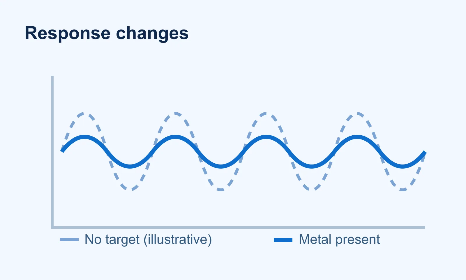
The target changes the coil/oscillator response evaluated by the electronics.
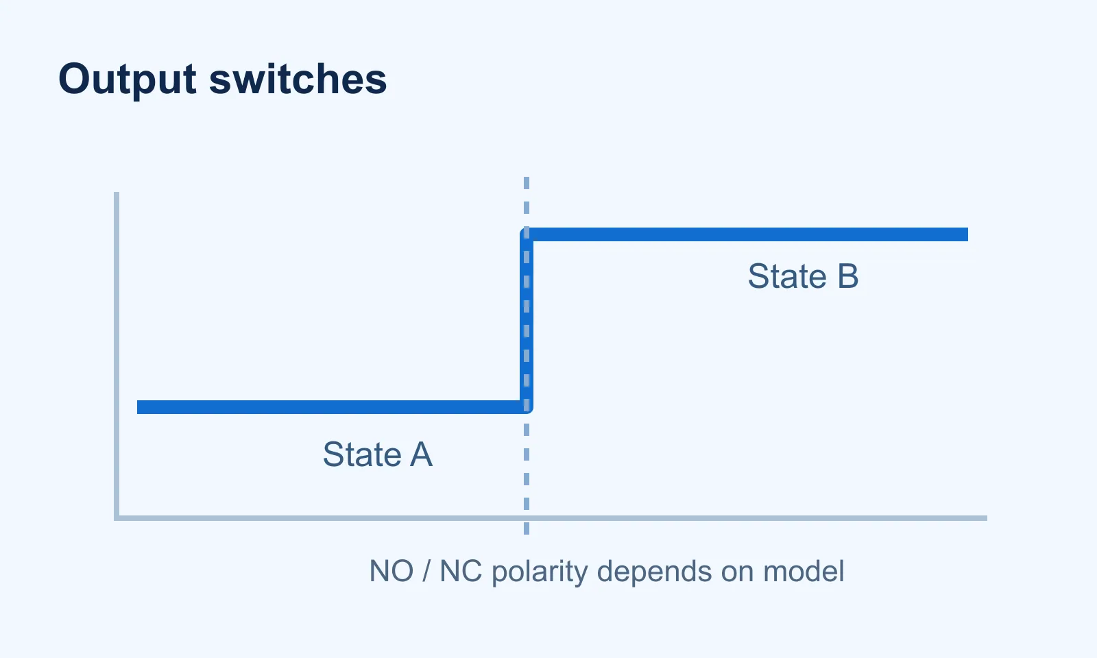
The specified NO, NC or configurable output changes at its switching point.
Which Inductive Sensor Types Are Available?
Housing geometry changes how a target passes the active area and how the sensor can be mounted. Match the shape to the physical path of the metal target; do not assume the same sensing-distance definition applies to every design.

A front-facing active area in a threaded or smooth round housing; useful where axial adjustment is needed.

A block-style housing with mounting options suited to space and target-approach constraints.
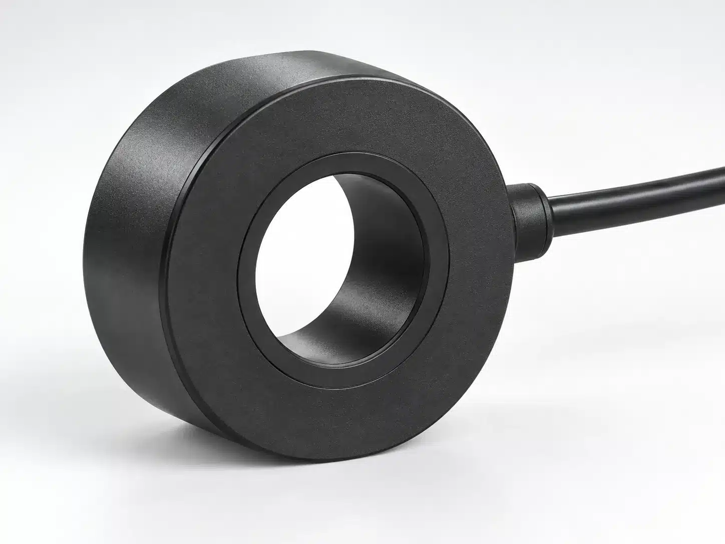
A metal part passes through the opening; commonly used for presence or counting tasks.

A metal target passes between the two sides of a U-shaped sensing opening.
How Far Can an Inductive Sensor Detect Metal?
The rated operating distance, often written sn, is a reference value established with a specified standard metal target and approach. It is not a guaranteed installation gap for every metal or part shape. For a dependable design, compare the exact model's assured or usable operating distance with the real target and mounting conditions.

- Target alloy and conductivity/permeability.
- Target area, thickness, shape and approach direction.
- Flush or non-flush mounting and nearby metal.
- Temperature, supply conditions and the particular sensor design.
| Datasheet term | What it describes | How to use it |
|---|---|---|
| Rated distance (sn) | Reference switching distance with a standard target; does not include all production variations. | Use for initial model comparison, not as the only installation gap. |
| Assured distance (sa) | A distance within which operation is assured under the stated specification conditions. | Look for this value or the manufacturer's equivalent when setting a reliable gap. |
| Material reduction factor | How the distance for a stated metal differs from the reference steel target on that model. | Apply only the factor documented for the chosen sensor and target material. |
| Hysteresis | Difference between the target approach and retreat switching points. | Allow for it when repeat position and chatter matter. |
How Do Target Material and Mounting Affect Detection?
Standard inductive sensors can detect ferrous and non-ferrous metals, but the switching distance may differ. A smaller target can also switch closer to the face than the standard reference target. Surrounding metal can pre-attenuate the field, especially if a non-flush model is mounted like a flush one.
Steel reference data cannot be copied directly to aluminum, copper or a small screw. Read the model's material factors and test the actual target at the intended approach path.
A flush-rated sensor may be embedded in metal as its manual permits. A non-flush design needs the manufacturer's specified clearance around its active face; do not use a generic multiplier for every model.
What Are the Advantages and Limits?
Inductive sensing is useful when the target is metal and non-contact switching is needed. The limits are just as important: target material, installation geometry and electrical interface determine whether a particular model fits.
- Detects a metal target without mechanical contact.
- Does not rely on target color or visible light.
- Offers housing, mounting and output choices for different machine layouts.
- Does not directly sense plastic, wood or glass as the target.
- Usable distance can be shorter for some metals or small targets.
- Nearby metal and incorrect mounting can alter switching behavior.
- Response, environment rating and interface are model-specific.
Where Are Inductive Sensors Used?
They are commonly used to detect metal parts, positions and passages in industrial equipment. The examples below describe possible detection tasks, not verified installations or a claim that any one sensor fits all four.
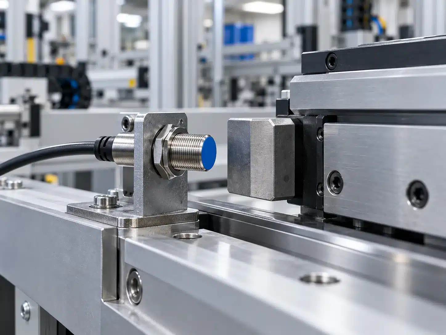
Confirm that a metal stop or machine component reaches a defined position.
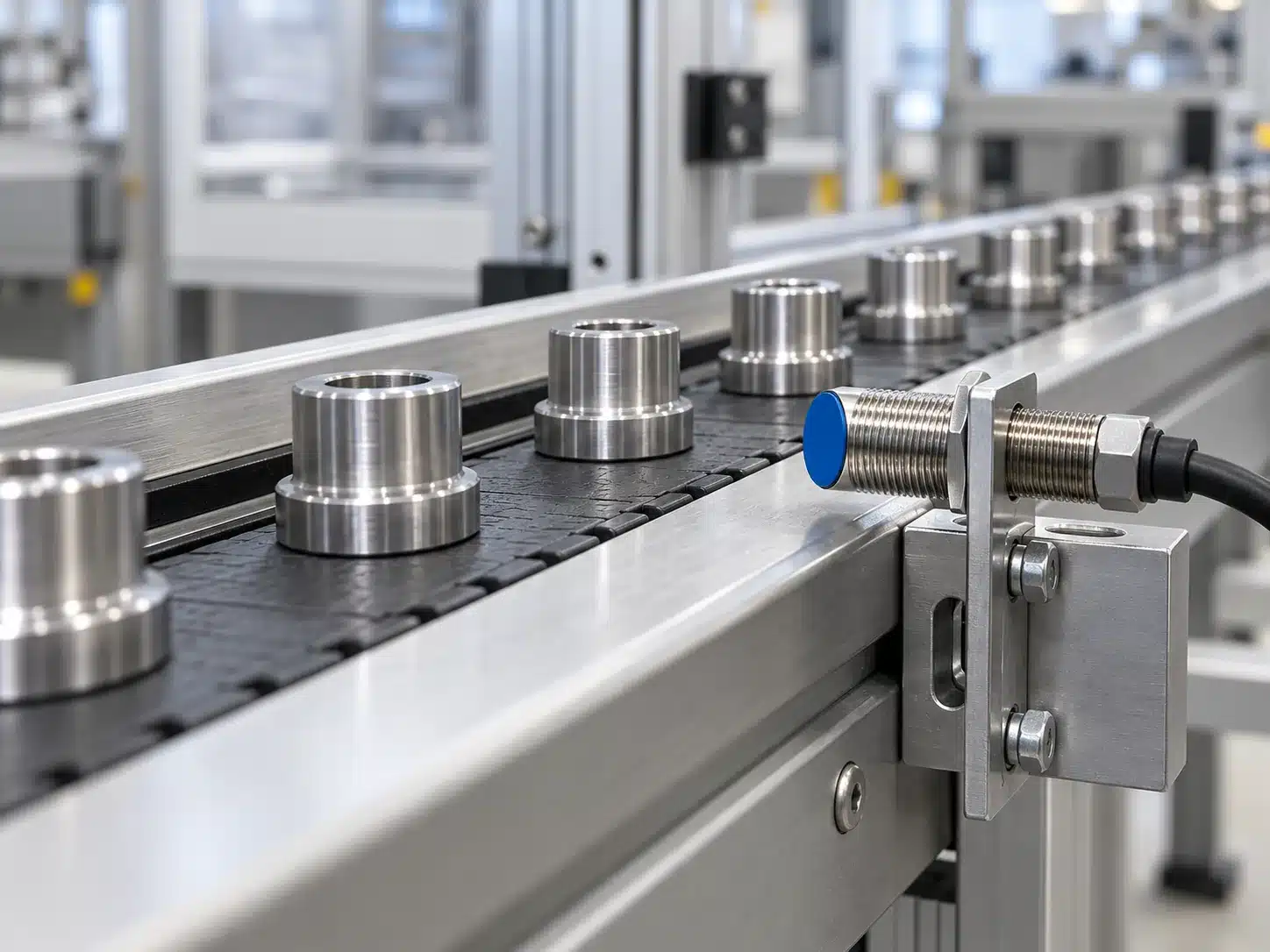
Register each metal item passing the sensing area, subject to event timing.

Provide process-position feedback from a metallic cam or machine member.

Signal metal-target presence to a compatible controller input.
Frequently Asked Questions
Can an inductive proximity sensor detect aluminum or stainless steel?
Often yes, but the achievable distance may differ from the value specified for the standard steel target. Read the exact model's material factor or all-metal claim and verify it with the actual part.
What is the difference between flush and non-flush mounting?
Flush-rated designs may be embedded in metal under their stated installation rules. Non-flush designs need a metal-free clearance near the active face; consult the selected model's mounting diagram.
Does a larger sensor always detect farther?
Housing size can influence coil size and available designs, but it does not define one universal range. Compare the rated and assured distances of actual models under matching target conditions.
Why is my sensor switching closer than the datasheet distance?
The target may be smaller or a different metal than the reference target, may approach from a different direction, or the surrounding installation may influence the field. Compare these conditions with the datasheet before diagnosing a fault.
Is an inductive sensor output always NPN and normally open?
No. The sensing principle does not fix the electrical output. Depending on the model, outputs can be NPN, PNP or other interfaces, with NO, NC or selectable switching behavior.