
How to Set the Cutoff Distance on a Background Suppression Sensor
To set the cutoff distance on a background suppression sensor, first establish where the target must be detected and which background must be ignored. Use the selected model's adjustment or teach procedure, then verify target-present and target-absent operation across the actual installation conditions. A successful teach confirmation is the starting point for validation, not the final acceptance result.

Before You Start
- Identify the exact sensor model, operating mode and available adjustment method.
- Have its manual, final mounting arrangement and representative production samples ready.
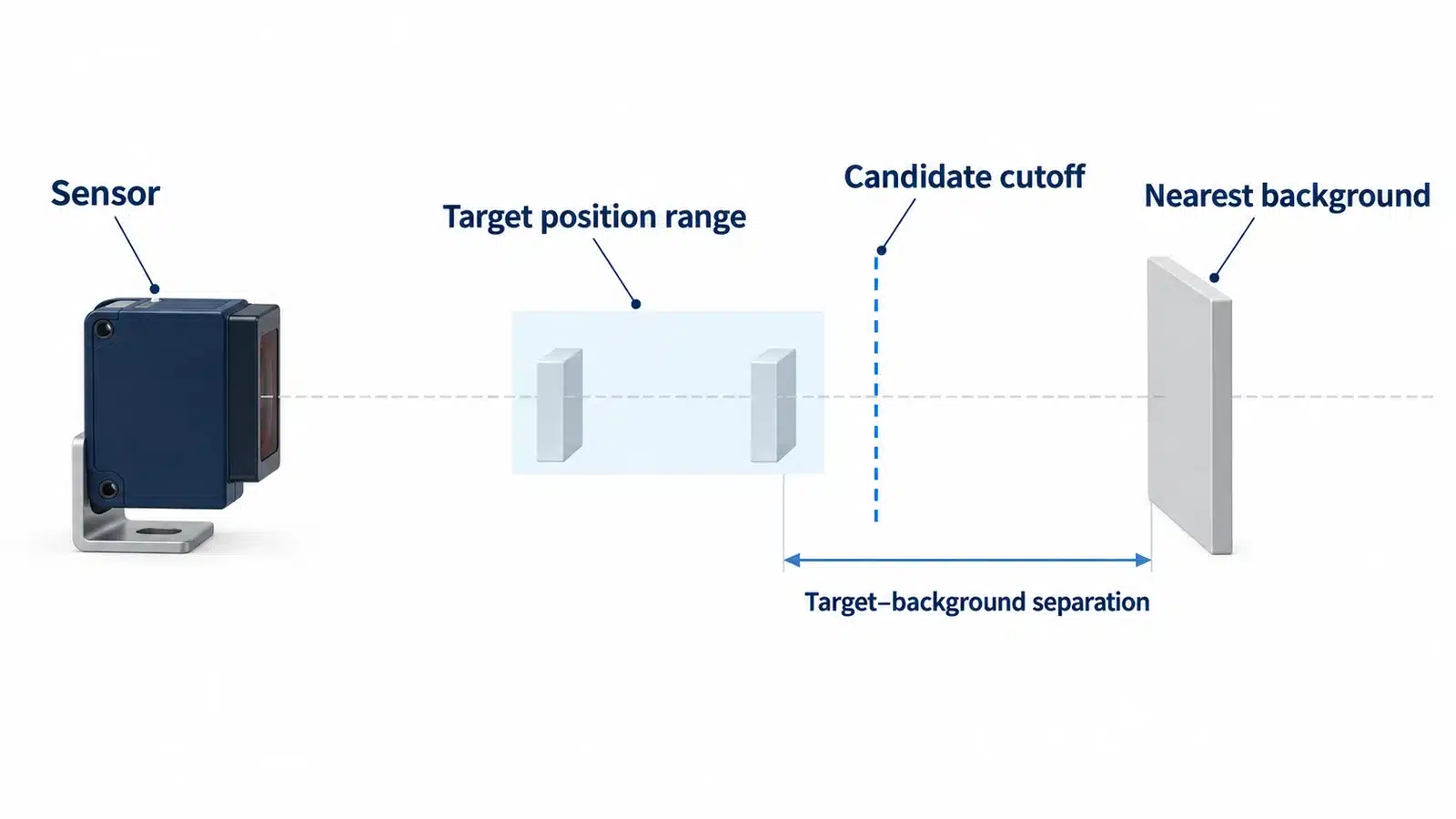
- Establish the target's permitted positions and the nearest background position.
- Decide which sensor output and controller input states should represent presence and absence.
What Cutoff Distance Means—and What It Does Not
A background suppression sensor uses distance-related information to distinguish a target in its sensing field from an object farther away. The cutoff is the selected far boundary used for that decision. It is not a physical barrier that makes every nearby object detectable or every distant reflection harmless.
In a triangulation-based design, the position of returned light on the receiver changes with object distance. That gives the sensor information beyond how much light comes back. Other implementations use different distance-sensing methods, so the setup controls and performance limits must be matched to the actual device.
The practical question is therefore broader than “What number should I set?” It is “Can one setting detect the required target conditions while rejecting the required background conditions?” That distinction determines how to commission the sensor.
Cutoff Setting, Minimum Range, and Target–Background Separation
Keep three distances separate. The cutoff setting defines the intended far detection boundary. The minimum sensing range is the near limit within which detection may not be specified. Target–background separation is the physical distance between the surfaces you need to distinguish. Moving the cutoff changes the decision boundary; it does not create more physical separation.
Measure target and background positions from the same reference identified in the sensor documentation. Do not mix a distance measured from a mounting bracket with one measured from the optical face. Likewise, a relative adjustment bar or dial position should not be treated as a calibrated millimeter reading unless the documentation defines it that way.
There can also be a difference between the distance where the sensor operates and where it resets as the target moves back. This is differential travel, often called hysteresis. It is distinct from a shift caused by a different target surface. For setup, the useful consequence is simple: check both approach and withdrawal, and do not position the required detection point right on a barely stable transition.
Step 1: Confirm the Sensor Mode and Adjustment Method
Read the complete model identification before touching the adjustment. A similar housing can contain a different sensing function, output or configuration interface. Confirm that the device is operating in background suppression mode and whether the cutoff is fixed, mechanically adjustable, teachable or configurable through a supported digital interface.
Next, identify what the available control actually changes. A button may select output logic, teach a reference or lock the controls. An adjustment labeled for sensitivity is not automatically a distance control. Changing an output function can reverse the indicated electrical state without improving target/background separation.
Use the manual to answer three specific questions: what condition must be presented, what indicates that the setting was accepted, and how does the sensor return to normal operation? If an attempt is rejected, check the stated failure indication before assuming the old setting has been replaced. Do not borrow a press duration or LED sequence from another product.
Before manipulating targets or mounts, put the machine into its approved safe setup condition. Plan subsequent powered motion tests under the machine's commissioning procedure. Optical setup is not a reason to defeat guarding or use an ordinary detection sensor as a personnel-protection device.
Step 2: Establish the Target and Background Conditions
Set up the sensor in its intended mounting position. A reading obtained while holding the sensor by hand does not establish the geometry of the installed machine. Secure the bracket, identify the sensing point and use actual target samples rather than choosing only the easiest surface to detect.
Locate the Farthest Target and Nearest Background
Determine the complete position range the target can occupy at the required detection point. Include the variation allowed by the guides, fixtures and part dimensions. Then identify what the sensor sees when no target is present: a belt, machine frame, backing plate or another moving component may become the background.
The farthest target and nearest background provide a useful first check of the available depth separation. They are not a complete optical acceptance test. Record those positions, then check whether the chosen sensor's documented operating range and separation requirements leave room for the application.
If the target and background occupy nearly the same depth, consider whether the mechanical arrangement can create a clearer distinction. Teaching cannot be assumed to compensate for inadequate separation. A more favorable mounting direction or a different detection location may be more useful than repeatedly adjusting the same threshold.
Check Surface, Angle, and Position Variations
The farthest target is not necessarily the most difficult target. Returned light also depends on the surface and its orientation. A glossy face can direct light away from the receiver; a different face on the same part can behave differently at the same distance. Background suppression reduces some background and color effects, but it does not eliminate the need to test the actual surfaces.
Build the setup check around the variations that occur in production: different finishes, expected tilt, lateral position and the background exposed between parts. If a target has several faces, present the faces that can actually cross the sensing point. Avoid validating only a flat, conveniently oriented sample when the machine presents it differently.
A useful diagnostic is to hold distance constant while changing the permitted surface or angle. If detection changes, distance alone does not explain the result. That observation helps you decide whether to adjust mounting, choose a more consistent sensing feature or investigate the sensor's suitability for the target.
Step 3: Set the Cutoff Using the Correct Procedure
Choose the applicable method below. Manual adjustment, single-point teach and two-point teach are alternative configuration approaches, not three operations to perform in sequence on every sensor. Keep the documented range limits and acceptance indications available during the adjustment.
Manual Adjustment: Find the Usable Setting Window
For a mechanically adjustable model, use its specified procedure to find the settings associated with target detection and background rejection. Note each observed transition instead of stopping at the first setting that detects one sample. Change one control at a time so that the effect remains interpretable.
Think of the result as a usable setting window: settings inside it satisfy both requirements under the conditions checked. Select a position within that window as directed by the manual, then test the remaining variations. An adjustment at the edge of the window deserves particular scrutiny because small changes in the installation may consume the remaining tolerance.
For example, the Q60AFV procedure compares two observed pointer settings and selects an intermediate position. That instruction belongs to that model. It does not establish a universal rule to calculate the cutoff as the arithmetic midpoint of target and background distances, or to turn every adjustment screw by the same fraction.
If no setting satisfies both requirements, record the conflict. Do not hide it by testing the target at one setting and the background at another. The final installation must meet both requirements with the same operating configuration.
Single-Point Teach: Confirm What the Sensor Is Learning
A single-point operation learns one presented reference condition. Establish whether that reference is supposed to be the target or the background. The resulting cutoff may be offset from the learned distance, so the reference position and the final switching boundary are not necessarily identical.
The QS30AF, for example, provides separate background and object-detection SET methods. Their purpose is different even though both involve presenting one reference. Follow the method selected for the application; do not assume that a successful target teach also demonstrates background rejection.
After teaching, return to normal operation and present the condition that was not taught. If the background was learned, check the required targets. If the target was learned, remove it and check the background. Then test the other permitted positions and surfaces. This closes the information gap left by teaching only one condition.
Two-Point Teach: Present the Required Conditions
A two-point procedure uses two samples of the sensing situation. Check what each sample represents and the required order. For the RightSight M30 static BGS teach procedure, the two conditions are target followed by background; its precision teach procedure instead keeps the target present for both samples. Those operations should not be interchanged merely because each involves two steps.
During a target/background procedure, keep the intended sensor mounting unchanged and present each condition deliberately. Do not accidentally teach a hand, temporary fixture or a background position that will not occur in service. Read the completion indication before proceeding.
If the teach fails, inspect the supplied conditions and the device's diagnostic meaning. Repeating the button sequence without changing an unsuitable condition is not a corrective action. Where the procedure succeeds, verify both states independently before testing movement.
Step 4: Validate Both Detection States in the Machine
Treat validation as a separate stage with a fixed setup. Re-adjusting between every sample can conceal a configuration that works for one condition but fails for another. If you change the cutoff, mode or mounting during validation, repeat the relevant checks using the new configuration.
Check Target-Present and Target-Absent Conditions
First present each required target condition at its permitted positions. Observe whether the sensor consistently reports the required detection state. Move the target through the approach and withdrawal path where relevant, rather than testing only a stationary point in the middle of its travel.
Next remove the target and expose the backgrounds that can occur in operation. Include the nearest background position and reflective surfaces identified during preparation. A sensor that detects every target but also responds to the empty machine has not passed the task.
Record exceptions precisely: which sample, position, angle or background caused the change? “Sometimes unstable” gives little direction. “Target disappears at its tilted position while the background-only state remains correct” identifies a different problem from “the empty shiny backing plate triggers detection.” Use that distinction to guide the next adjustment.
Verify Moving Targets and the Controller Input
After static checks, test through the permitted production sequence and speed range using the machine's safe commissioning process. Watch the required detection feature enter and leave the sensing region. A static setup establishes separation at rest; it does not establish whether both output transitions occur in time for the application.
Response time describes the delay between an optical change and the output operating or resetting. Configured delays and the receiving input's requirements also belong in the check. Verify the selected sensor settings and actual controller behavior rather than inferring successful capture from a visible indicator alone.
Compare observations in sequence: the target event, the sensor output and the controller's recorded state. If the output changes correctly but the controller does not register it, investigate the electrical interface, input configuration and event duration. If the sensor output itself is wrong, return to the optical and timing checks. Increasing the cutoff is not a general solution to a downstream input problem.
What to Check When No Stable Cutoff Setting Works
Use the symptom to choose a test that separates possible causes. The following table is a diagnostic starting point, not proof that any one cause is present.
| Observation | What to distinguish | Next check |
|---|---|---|
| Target is detected only after the background also triggers | Inadequate usable separation versus unsuitable target return | Compare target and background transitions with unchanged mounting; check the model's range and separation conditions. |
| One finish or angle fails at the same position | Surface-related return versus distance variation | Hold position constant and compare permitted surfaces and orientations. |
| Empty machine triggers intermittently | Moving or reflective background versus a stable background | Observe the background-only cycle and isolate the surface or position associated with the event. |
| Teach is rejected or its result is unclear | Wrong procedure, invalid reference condition or device diagnostic | Confirm the mode, presented condition and exact acceptance/failure indication. |
| Static detection passes but running detection fails | Optical change during travel versus timing/capture failure | Compare the moving target, sensor output and receiving input; check the actual configured timing. |
When the same target is repeatedly marginal, improving its presentation can be more effective than extending the setting. When the background is the problem, inspect its position and reflective geometry. Any change to the sensor angle or detection location must be followed by target and background validation; an improvement for one state can affect the other.
If the installation offers no workable separation with the selected sensor, take the observations back to model selection. Specify the actual sensing problem, including difficult samples and background conditions, instead of requesting only a longer range. A longer advertised range does not by itself demonstrate that two nearby surfaces can be distinguished.
Record the Final Setup Before Production
Keep a setup record that another technician can reproduce. Include:
- Complete sensor model and suffix, operating mode and configuration interface.
- Mounting reference, sensor orientation, target position range and nearest background position.
- Cutoff setting or saved parameters, taught conditions and the samples used.
- Output logic, timing settings and the receiving controller input configuration.
- Target-present and target-absent observations across the tested positions, surfaces and production conditions.
- Remaining limitations, agreed acceptance criteria and the person/date responsible for the test.
Use a test duration and sample coverage appropriate to the machine's acceptance plan; there is no universal pass count for every application. Record what was tested rather than turning a short trial into a claim of guaranteed production reliability.
Recheck the setup when a change can affect the sensing conditions, such as a new part finish, altered guides, a replaced sensor, a moved bracket or changed timing. Save the accepted configuration before making later adjustments so that changes remain traceable.
If model suitability remains uncertain, send the supplier the setup record, representative samples and the specific failed condition. That gives a useful basis for choosing or testing a sensor. The final decision should rest on documented model limits and demonstrated separation in the intended installation, not on a cutoff number alone.
Technical Sources
- Banner Engineering — Q60AFV Series Sensors with Visible Red Emitter, 69622 Rev. D, 18 October 2021. Adjustable-field operation, manual cutoff setup and reflective-background limitations, pp. 2–4.
- Banner Engineering — QS30AF Adjustable Field Series Sensor, 19 August 2025. Single-reference SET methods and minimum-range considerations, pp. 7–8.
- Rockwell Automation — RightSight M30 Background Suppression and Reflection Sensor Installation Instructions, 42AF-IN002C-EN-P, August 2021. Configuration variants, static/precision teach and target/background separation, pp. 1–2.
- OMRON — Photoelectric Sensors: Explanation of Terms. Set range, sensing range, differential travel, dead zone and response time; accessed 16 October 2026.
- OMRON — Photoelectric Sensors: Operating Principles and Selection Points. Triangulation, surface effects and application conditions; accessed 16 October 2026.