
How to Read a Sensor Datasheet: Output, Sensing Distance, Housing and Protection
Read a sensor datasheet by confirming the exact model first, then checking its output and electrical limits, sensing conditions, mechanical interfaces and environmental ratings together. A headline distance, housing size or IP code cannot establish whether the sensor will suit your detection point.
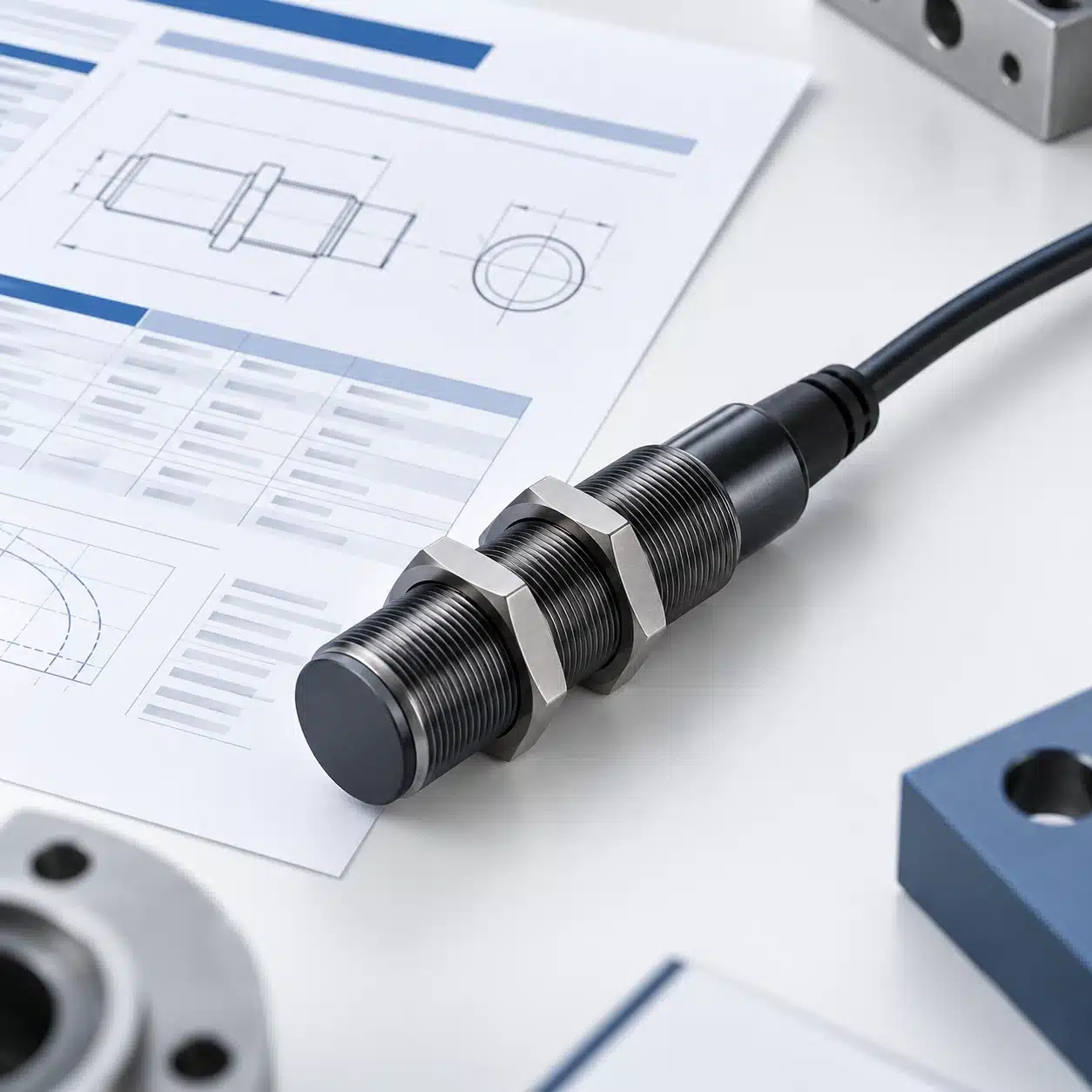
For industrial switching sensors, turn each entry into an application decision: what does the specification establish, under which conditions, and what remains unproven? This guide focuses on proximity and photoelectric sensors used in automated equipment.
Quick Reading Order: Check These Fields First
Start with the fields below before comparing headline specifications. The table is a reading map: later sections explain how to interpret the entries and where an apparently suitable specification can mislead.
| Read first | What to establish | Read alongside it |
|---|---|---|
| Complete model and document revision | The exact variant covered by the data | Order-code key, applicable notes and related manual |
| Output and electrical ratings | How the output switches and what the circuit permits | Supply range, load limits, voltage drop and receiving-input requirements |
| Sensing distance and conditions | What target and test arrangement the distance describes | Target material, size, optical arrangement and mounting restrictions |
| Housing, mounting and connection | Whether the sensor and its interfaces fit | Dimensioned drawing, installation instructions and connection diagram |
| Protection and temperature | Which environmental conditions are covered | Materials, exposure restrictions, connector sealing and approval-specific notes |
| Timing and remaining footnotes | Which dynamic or special conditions still need checking | Operation/reset timing, switching-frequency conditions and controller input behavior |
Confirm the Exact Model and Datasheet Conditions
Use the complete order code, including suffixes. A series page can describe several outputs, connectors or sensing arrangements, while the unit you are buying has one particular configuration. A family feature list does not prove that every version includes every feature.
Next, identify the document revision and any linked installation instructions. Keep that version with your design or purchasing record so a later comparison refers to the same specification. If the order code on the quote differs from the one on the datasheet, resolve the difference before comparing performance.
Read the column heading, unit and footnote as one statement. A maximum value describes a limit; a typical value describes representative behavior under stated conditions. A typical figure alone does not establish the worst case your design must accommodate. Similarly, an operating-temperature range and a storage-temperature range describe different situations.
Pay attention to the scope of each note. A table-wide condition may qualify several rows, while a mark beside one value may apply only to that entry or a particular approval. The number is incomplete until you know which conditions belong to it.
Read the Output and Electrical Ratings Together
NPN/PNP, NO/NC, and Output Mode
For a common three-wire DC transistor output, PNP describes a sourcing output and NPN a sinking output. The distinction concerns current flow through the external load. In the corresponding basic circuits, a PNP load is connected toward the negative supply, while an NPN load is connected toward the positive supply. The sensor and receiving input must form the intended circuit.
Normally open (NO) and normally closed (NC) answer a different question: when does that output conduct? For an ordinary proximity switch, NO normally becomes active when the specified target is detected; NC normally behaves in the opposite way. Confirm the selected model's operating diagram, especially if its function is selectable. PNP does not mean NO, and changing output polarity is not a substitute for choosing the required switching function.
Photoelectric sensors may describe operation as Light-ON or Dark-ON. These labels refer to received light. An object can reduce received light by interrupting a beam, or increase it by returning light to a diffuse sensor. Therefore, “object present” cannot be assigned to Light-ON or Dark-ON without identifying the optical arrangement.
Read the circuit type, operating function and connection diagram together. For a candidate marked PNP NO, first establish whether the receiving input accepts a sourcing signal; then check which target state activates the output and whether the input recognizes both states. Supply-voltage compatibility alone does not answer either question. XSZ's output-type guide explains the output families, while the exact sensor and controller diagrams determine a real connection.
Supply, Consumption, Load Current, and Voltage Drop
The supply-voltage range tells you what may power the sensor. Current consumption describes the sensor's own electrical demand under the stated conditions. The output-current rating describes a different limit: the load that the switching output is permitted to carry. A low-consumption sensor does not necessarily have a low output rating, and the output rating is not the amount of current it forces through every connected input.
The load and receiving circuit determine the actual output current. Check that this current is within the sensor's applicable rating and that the receiving input can recognize the resulting states. Where the datasheet lists a minimum load or off-state leakage current, include those conditions rather than checking only the maximum load figure.
Output voltage drop matters because an active semiconductor output is not an ideal closed contact. Some voltage remains across the output stage when it conducts. Consequently, “output ON” does not automatically mean that a receiving terminal sees an ideal supply-rail voltage. Read the stated voltage drop with its load conditions, then compare the available signal with the input's specified ON and OFF requirements.
A supply match is therefore only the first electrical check. It does not establish output compatibility, and a matching connector does not resolve a circuit mismatch.
Interpret Sensing Distance in Its Test Conditions
Rated, Real, and Assured Operating Distance
For inductive sensors, the nominal or rated sensing distance is a reference designation under defined conditions. It is not a measurement of the particular unit installed on your machine. A real sensing distance describes an individual device under specified reference conditions; other distance entries account for stated variations such as supply and temperature. An assured operating distance identifies a region covered under the manufacturer's defined conditions.
Manufacturers may use different field names. Record the exact distance entry, its reference target and stated conditions before comparing it with the machine gap. When the same sheet lists a headline sensing range and a separate operating-distance range, use the latter for the documented operating-region decision; the headline value does not replace it.
This changes how you read an installation gap. Start with the applicable operating region, then account for the actual target and permitted movement. A part that moves toward and away from the sensor must remain distinguishable throughout the intended positions; placing the nominal gap at an observed switching boundary leaves that movement unaccounted for.
Also distinguish hysteresis from repeatability. Hysteresis concerns the difference between the switching positions during approach and withdrawal. Repeatability concerns how consistently switching occurs when the same conditions are repeated. Neither term, on its own, guarantees detection throughout an arbitrary target path.
Target Material, Size, and Optical Reference Conditions
An inductive distance specification belongs to a stated target and arrangement. Changing the metal, target dimensions or direction of approach can change the switching behavior. A rating established with a reference target cannot simply be assigned to a smaller production feature. Use the selected model's applicable target information; do not apply one universal correction factor to all metals and sensors.
Photoelectric distance requires a different reading. A through-beam arrangement describes separation between an emitter and receiver. A retro-reflective arrangement includes a specified reflector. A diffuse arrangement receives light returned from the target, so its reference object and surface characteristics are part of the specification.
For diffuse sensing, a distance obtained with a reference white target does not establish the same result for a small, dark or differently oriented production part. The return reaching the receiver changes with the object and geometry. Where engineering curves are supplied, check the target used to generate them before using them to assess your application.
The distance number is useful only after its reference conditions are understood. Compare those conditions with the real target, and identify which differences require model-specific information or a sample check. Do not transfer inductive distance relationships to optical sensing simply because both tables use millimeters.
Read Housing, Mounting, and Connection as Separate Specifications
Body Size, Thread, and Installation Clearance
Housing dimensions answer whether the body can fit; mounting instructions answer how it may be installed. For a threaded body, read the thread designation and usable mechanical dimensions from the drawing. Also identify the sensing face: a dimension measured from the connector end does not necessarily describe the location from which a sensing gap is specified.
For inductive sensors, flush or non-flush mounting is a functional installation condition, not merely a cosmetic difference. Nearby metal can affect the sensing arrangement, so follow the selected model's mounting requirements instead of assuming that any sensor of the same body diameter can occupy the same bracket position.
Allow space for the complete assembly: nuts or brackets, the target's movement, the mating connector and the cable route. A body that fits an empty opening may still be impractical once a connector is attached or adjustment is needed. The drawing and installation instructions should resolve that question before the housing designation becomes a purchasing specification.
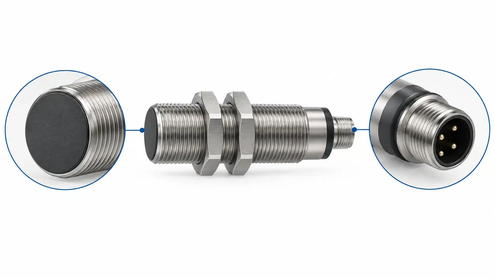
Connector Type, Pin Assignment, and Cable Requirements
An M12 body thread and an M12 electrical connector describe separate interfaces. Even when both appear on one datasheet, one identifies mechanical mounting and the other identifies a connection. The repeated size designation does not establish pin function.
For the connection, check the connector family, coding, contact count and actual assignment. Then match the sensor diagram to the mating cable and receiving circuit. Do not infer the functions of the pins from connector size alone, or assume that a familiar cable color always proves a particular electrical connection.
Cable requirements also belong to the installation. Check the specified cable construction and routing limits against movement, temperature and exposure at the detection point. If the datasheet does not answer whether the proposed cable or mating assembly is suitable, keep that item unresolved rather than treating connector fit as complete compatibility.
Understand What Protection Ratings Do—and Do Not—Cover
IP Rating, Temperature, and Chemical Exposure
The IP code identifies enclosure protection against specified ingress conditions. Its first digit concerns solid objects or dust; its second concerns water. IEC 60529 is the enclosure-protection standard associated with this code. These are defined protection categories, rather than a general score for every industrial environment.
For IP67 specifically, 6 denotes dust-tight protection and 7 protection against temporary immersion in water under specified conditions.
An IP67 entry therefore does not, by itself, establish suitability for hot cleaning jets, cutting oil, a particular solvent or prolonged exposure outside the documented conditions. Water ingress and material compatibility are different questions. A housing can meet a stated ingress requirement while the intended chemical still needs a separate compatibility check.
Read the temperature range independently, including any qualifications. A high IP designation does not raise the allowed operating temperature. Likewise, listing a housing material does not prove that the sensing face, cable jacket, seals and connector all tolerate the same exposure.
Describe the actual environment when seeking clarification: the fluid or cleaner, concentration where relevant, temperature and exposure pattern. This gives the supplier a specific condition to assess instead of the ambiguous request for a “waterproof sensor.”
Connection Conditions and Approval-Specific Limits
Check whether the published protection depends on the connection being correctly assembled. An enclosure rating cannot establish the protection of an open connector or an unsuitable mating assembly. Read the manufacturer's sealing and installation conditions for the complete installed connection.
Approval notes also need their own scope check. A general ambient-temperature entry may differ from the conditions stated under a particular approval. Do not use the broader headline range to override a narrower applicable note. Identify the exact variant and the conditions required for the approval relevant to your application.
A standard number in a catalog identifies a reference; it is not independent evidence that every product in a family has every associated certification. Keep the product documentation and any required conformity evidence tied to the selected order code.
Real Example: How to Interpret an Industrial Sensor Datasheet
The official ifm IFS204 datasheet, revision IFS204-02 EN-GB dated June 26, 2025, provides a useful reading example. It identifies the device as IFB3004BBPKG/US-104. The figures below belong to that exact third-party model; they are not XSZ specifications or a product recommendation.
| Field group | Published entries for IFS204 | Reading implication |
|---|---|---|
| Output | PNP; normally open | Circuit type and switching function are separate selections. |
| Electrical | 10–30 V DC supply; consumption below 10 mA; permanent switching-output rating 100 mA; maximum DC output voltage drop 2.5 V | Own consumption is not the load rating. Check the receiving circuit and applicable load conditions. |
| Detection | Sensing range 4 mm; real range 4 mm ±10%; operating distance 0–3.24 mm | Do not replace the operating-distance entry with the headline range. Target and installation conditions still apply. |
| Body and mounting | M12 × 1 threaded body; listed length 45 mm; flush mounting | Read the mechanical drawing and mounting requirements together. |
| Connection | M12, A-coded, three contacts | This is a separate interface from the body thread; use the connection diagram. |
| Environment | IP67; general ambient range −25 to 70 °C | Check exposure and any additional approval-specific conditions separately. |
Worked decision: can a proposed 3.5 mm gap be accepted? Suppose the largest target-to-face gap in a proposed installation is 3.5 mm. This is an application assumption, not a test result for IFS204. The datasheet's 4 mm sensing range is the headline value; its listed operating distance is 0–3.24 mm. The proposed maximum gap exceeds the top of that published operating range by 0.26 mm. A sample might switch at 3.5 mm, but that observation would not put 3.5 mm inside the documented operating range.
- Distance — not a documented match at the proposed gap. Do not approve the 3.5 mm position by comparing it only with the 4 mm headline. Reduce the worst-case gap or assess another exact model whose applicable operating region covers it.
- Target and mounting — still to verify. Identify the production target's material, smallest effective area, approach path and any nearby metal. The listed distance does not establish behavior for every such target and installation.
- Electrical and assembly — separate checks. The PNP NO output and 10–30 V DC supply must match the actual receiving input and supply; check the load limits, M12 connector assignment, flush-mount requirements and installed cable clearance.
- Decision — test after the documentation check. If a revised candidate appears suitable on paper, validate detected and undetected states with representative parts and the installed controller under operating conditions. A passing sample test supplements the documented limits; it does not rewrite them.
The example shows how a datasheet can rule out a proposed placement before a production trial. It is not a recommendation of this third-party model or a claim about any XSZ sensor.
Sensor Datasheet Selection Checklist: From Specifications to Application
After reading, separate what the document establishes from what your application still needs to demonstrate. Use the following sequence to make that distinction practical.
- Record the exact candidate. Keep its complete order code, datasheet revision, relevant drawings and applicable notes together. If the quoted configuration is different, resolve it before proceeding.
- Write down the real detection conditions. Describe the target material and smallest relevant feature, its permitted positions and motion, mounting surroundings, and any optical background or reflector. Compare these with the conditions behind the distance entry.
- Check the electrical interface as a complete circuit. Compare the output type and operating function with the receiving input, then check supply, load-related limits and voltage levels. Leave an unknown pin assignment unresolved until the correct diagram is available.
- Review the installed assembly and exposure. Include mounting clearance, the mating connection, cable route, operating temperature and actual contaminants. A matching body size or IP code cannot close these items on its own.
- Check dynamic behavior before acceptance. Look for operation and reset times and the conditions behind any switching-frequency figure. Response time concerns an output transition; switching frequency concerns repeated operation under specified conditions. Do not turn a headline frequency into an allowed production rate without checking target timing and the receiving input's capture behavior.
- Record a disposition for every critical requirement. Note the exact datasheet field and revision, the real application condition, and one result: documented match, application test needed, incompatible or unknown. Resolve incompatible or unknown items before purchasing approval. For a required test, define representative parts, permitted gaps and motion, environment, and the detected and undetected controller states that count as a pass.
When asking a supplier to identify a suitable model, send the target material and smallest relevant feature, minimum and maximum gap, mounting space, output/input requirements, supply, connection, exposure and timing conditions. Request the exact model datasheet and connection drawing for any proposed option. XSZ's inductive proximity sensor category is a starting point for inductive products; a category description does not establish the specifications of an individual model.
Technical Sources
- ifm — IFS204 datasheet, IFS204-02 EN-GB, June 26, 2025. Exact-model reading example, pages 1–3.
- Pepperl+Fuchs — Operating distance as central characteristic. Inductive distance definitions and influence factors.
- Pepperl+Fuchs — 3-Wire Sensors. Sourcing and sinking output principles.
- OMRON — Photoelectric Sensors: Explanation of Terms. Optical distance, response and operating-mode terminology.
- OMRON — Photoelectric Sensors: Further Information. Reference targets and target-dependent detection conditions.
- OMRON — Proximity Sensors: Explanation of Terms. Switching function, response frequency and mounting terminology.
- IEC — IEC 60529:1989 publication record. Official identity and scope of the IP-code standard.
- OMRON — Degree of Protection. Ingress-protection and installed-connection precautions.
- OMRON Australia — IP Rating Reference Guide. Product-specific checks for oil and chemical exposure.