
How to Mount and Align a Rectangular Photoelectric Sensor
Mount the sensor on a stable support with its optical axis at the required detection point. Align it using the procedure for its sensing method, then secure the hardware and check both target states. Finish by confirming that the machine controller detects the actual parts at operating speed.
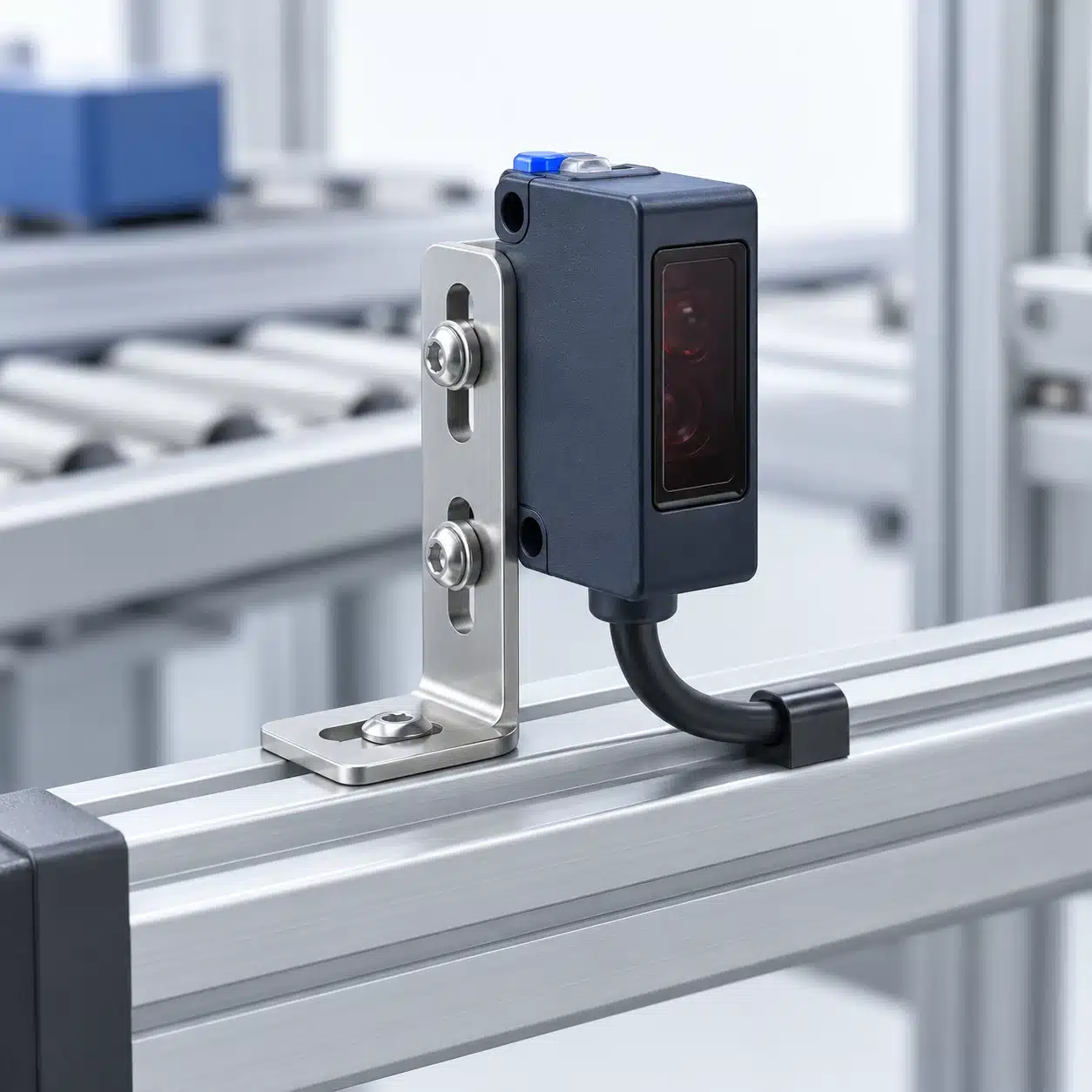
Before You Start: Confirm the Sensor and Detection Task
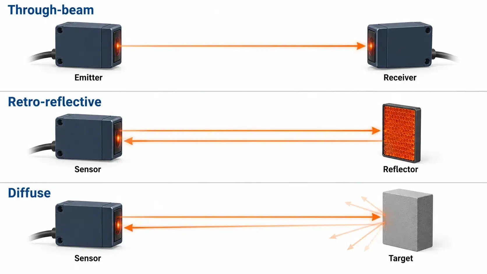
A rectangular housing describes the sensor's shape, not its optical arrangement. Similar-looking units may detect light from an opposite emitter, a reflector or the target itself. Identify that arrangement before deciding where to place the bracket or how to interpret an indicator.
Prepare the following before installation:
- Exact model and instructions: confirm the sensing mode, working range, any minimum distance and the meaning of each indicator.
- Mechanical drawing: locate the optical axis, mounting holes and permitted fasteners. Obtain the specified tightening torque rather than borrowing a value from a similar housing.
- Actual targets: include the smallest relevant feature and the positions, colors and finishes the equipment must handle.
- Optical accessories: identify the matching receiver or reflector where required, including its mounting space.
- Electrical information: confirm supply, output circuit, switching function and the receiving input's requirements.
- Commissioning arrangements: establish how the machine can be positioned, powered and tested without exposing people to hazardous movement.
Isolate hazardous energy before mechanical work or wiring. Powered alignment and motion tests belong in the machine's authorized commissioning procedure, with appropriate safeguards in place. Ordinary workpiece-detection sensors must not be treated as personnel-protection devices.
Choose the Mounting Position and Secure the Bracket
Place the Optical Axis at the Required Detection Point
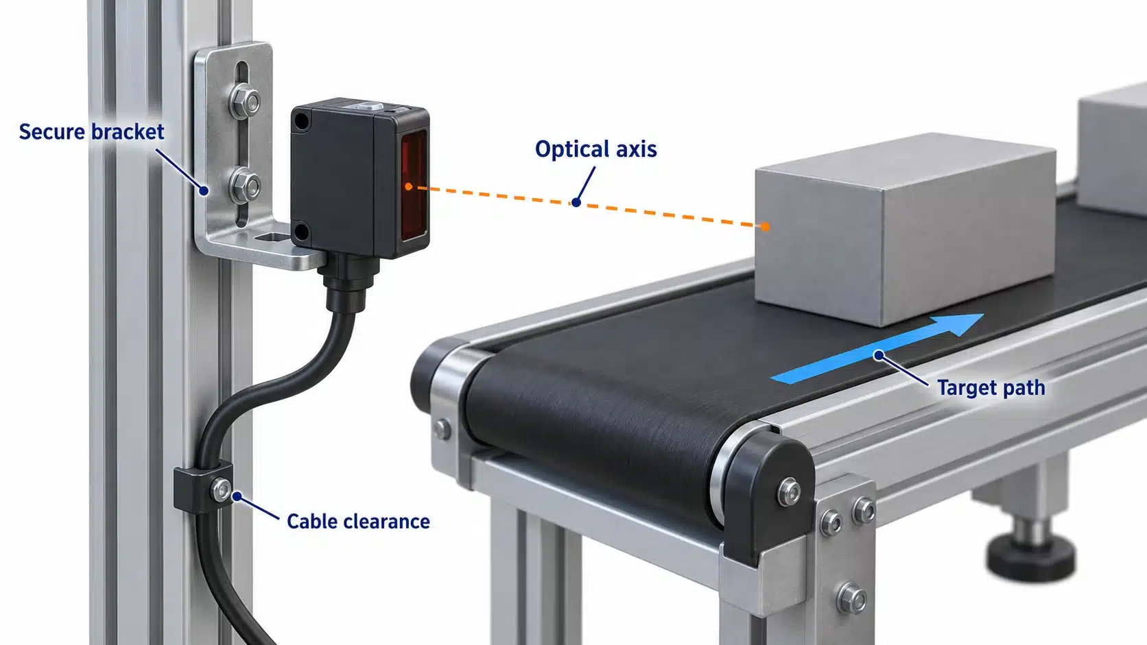
Start with the feature that must trigger the machine. The useful location is where that feature can be detected throughout its permitted movement, rather than simply where the housing is easiest to attach. Use the dimensional drawing to locate the optical axis; do not assume it lies at the center of the case.
Map the target's travel through the detection point, including normal sideways movement and height variation. For beam-interruption arrangements, check that the required feature interrupts enough of the effective beam. For diffuse sensing, check that the illuminated area remains on the intended target surface. A beam aimed near an edge may see the target at one position and the background at another.
Choose a support that holds the sensor's position relative to this path. A long, flexible bracket can change the angle even when its fasteners remain tight. Consequently, tightening screws harder is not a reliable cure for bracket movement. Change the support or mounting location when the geometry cannot remain stable.
Secure the bracket to the machine using the documented hardware. Where the mounting system permits adjustment, keep the sensor retained but adjustable until optical alignment is complete. Do not run production with loose mounting hardware.
Leave Room for Adjustment, Wiring and Maintenance
Check the space around the installed assembly, not just the case outline. You need access to the adjustment mechanism, indicators and fasteners, as well as clearance to remove a connector without disturbing the sensor. An opposing receiver or reflector needs the same practical attention.
Plan the cable route before fine alignment. Support the cable so its weight or movement does not pull the housing toward a different position. Follow the cable's bend and movement limits, and use a cable suitable for repeated flexing where the installation requires it. A cable loop that fits while the machine is stationary may pull tight at the end of travel.
Keep the optical face accessible for inspection and cleaning. If maintenance requires loosening the sensor, the setup will need to be checked again afterward. Allowing access at installation is usually more useful than trying to preserve a difficult-to-reach adjustment indefinitely.
Align the Sensor for Its Sensing Method
Use the indicator meanings and adjustment procedure for the exact model. A light-received indicator, an output indicator and a stability indication provide different information. Some sensors have no user adjustment; others use gain, distance setting or a teach sequence. The following sequence explains what to establish, rather than prescribing identical controls for every unit.
Through-Beam: Align the Emitter and Receiver
With the target clear of the beam, establish a direct optical path between the emitter and receiver. Both units must face the intended path. Adjusting only the receiver may leave the emitter pointing near the edge of the receiving area.
Where the manual permits this method, move each unit through the vertical and horizontal receiving range and position it away from the switching boundaries. The first angle at which an indicator changes is a useful boundary to find, but a poor place to stop. A small subsequent shift can move the setup back across that boundary.
Check the actual target across its permitted path after establishing reception. A large test card may block the beam successfully while the production feature does not. Verify the required interrupted and clear states using the real part and gap. Follow the model's prescribed gain procedure; maximum sensitivity or an added aperture is not a universal alignment instruction.
Retro-Reflective: Align the Sensor and Reflector
First establish a clear return path from the specified reflector. Mount the reflector securely and adjust the arrangement according to the sensor's instructions. A shiny machine surface is not an interchangeable substitute for a compatible retroreflector.
Once reception is established, pass the actual target through its expected positions. Check that detection changes when the part enters and returns to the required state when it leaves. If a shiny target returns enough light to mask the interruption, aiming more carefully may not solve the underlying sensing problem. Verify the suitability of the sensor's optical design and reflector combination.
Transparent targets also need a suitable sensing configuration and setup. Successful detection of an opaque hand or card does not qualify the same installation for a clear container. Use representative samples before fixing the final arrangement.
Diffuse and Background Suppression: Set Up with the Actual Target
A diffuse sensor uses light returned by the object. Place the actual target at its working position before adjusting the available sensitivity or teach setting. Then remove it and check the background. A setting that detects a part but also detects the belt behind it cannot distinguish the required states.
Evaluate the target that gives the weakest useful return within the expected operating conditions. Distance, surface finish and inclination can change that return. Increasing sensitivity may recover a difficult target while also making a background detectable, so adjustment must be judged against both conditions.
Background suppression, or BGS, uses a distance-related boundary to separate the target from more distant objects. Check whether the model has a fixed field, an adjustable cutoff or another setup method. A gain control and a cutoff-distance control do different jobs and should not be treated as interchangeable.
For an adjustable BGS installation, evaluate the farthest required target position and the nearest background position using the model's setup procedure. The two need sufficient separation for that sensor and those surfaces. If no setting consistently distinguishes them, reconsider the geometry or sensor suitability rather than treating a single successful sample as completion. Also follow any specified orientation relative to target movement; there is no universal tilt angle for rectangular sensors.
Check Backgrounds, Reflections and Nearby Sensors
Test Target-Present and Target-Absent Conditions
After basic alignment, challenge the installation with the conditions it must distinguish. Check representative parts at the allowed extremes of position and orientation. Then remove the part and leave the real background, fixtures and neighboring objects in place.
These checks answer different questions. A missed target means the required optical change did not reliably produce the expected state. An unwanted detection with no target present means another condition can produce that state. Raising sensitivity to solve the first problem can worsen the second in a diffuse arrangement.
Include normal changes in surrounding light and reflective machine positions where they affect the detection point. If the background moves during a cycle, checking only its parked position leaves part of the operating condition untested. Choose the final position and adjustment from the required range of conditions, not from the easiest sample.
Separate Optical Interference from Electrical Problems
An adjacent emitter can introduce light into a receiver. Electrical interference can also disturb a sensor circuit, but it enters through a different route. Changing optical sensitivity without identifying the route can obscure the cause.
Under a controlled test procedure, compare behavior with neighboring optical sources isolated one at a time, where this can be done safely. Record whether the disturbance follows a particular emitter or optical path. If it does, review positioning, separation, screening or the model's interference-prevention provisions.
Separately, check whether the symptom coincides with switching electrical loads or cable movement. Inspect supply, connections and cable routing, including separation from power wiring as required by the installation instructions. A correlation identifies a useful test direction; it does not prove that a particular sensor or drive has failed. Do not add unverified grounding or filtering changes as a shortcut.
Tighten the Mounting and Verify the Complete Signal
Recheck Alignment After Final Tightening
Hold the established position while securing the hardware to the documented limits. Watch for housing rotation or bracket movement as the fasteners are tightened. Then release any hand support and check the states again with the cable in its final route.
If the result changes after tightening, compare the optical position before changing sensitivity. An adjustment that compensates for a shifted bracket can conceal the mechanical problem. Restore the intended position and repeat the target checks.
Do not choose tightening torque from screw size alone. The sensor housing, inserts, bracket and specified hardware determine the permitted assembly. If that information is missing, obtain it before final installation rather than assuming a value used on another model will be suitable.
Confirm Switching Logic and Controller Detection at Operating Speed
Check the sensor indication, electrical output and controller input as separate points in the detection chain. Confirm which output state is required when the target is present and absent. Light-ON and Dark-ON refer to the optical condition; the relationship between received light and target presence differs between sensing methods.
For transistor-output variants, match NPN or PNP to the receiving circuit. For a relay-output variant, verify its contact arrangement and load requirements instead. Use the exact wiring diagram. The XSZ output-type guide identifies the interface details to review, but does not replace the selected model's diagram.
Begin with controlled static state checks, then run representative targets at the intended speed under the machine's commissioning procedure. Confirm the result at the controller, not only at the sensor LED. A part may create an optical event that is too short for the configured input to recognize. If static detection succeeds but moving parts are missed, inspect output timing, input filtering and capture configuration alongside the target's passage through the beam.
Use the actual sensor and controller documentation for timing limits. Do not infer a permissible production rate from an indicator flash or assume that optical alignment alone proves reliable counting.
Troubleshoot Unstable Detection After Installation
Use the symptom to choose a check that separates plausible causes. Change one setup variable at a time and retain the original settings so the result remains interpretable.
| Observed symptom | Possible setup cause | Check that separates the causes | Next action |
|---|---|---|---|
| Detection changes after tightening | Sensor rotation, bracket movement or cable pull | Compare beam position and states before and after securing the assembly | Correct the mechanical position, then repeat alignment |
| Output indicates a target after the part leaves | Background return, another object or incorrect switching interpretation | Test the empty detection area and compare optical indication with the configured output function | Correct the optical separation or logic as indicated |
| Detection varies between part surfaces | Different returned light or an unsuitable setup point | Test actual finishes at the permitted positions with the background unchanged | Reassess adjustment and sensing suitability |
| Disturbance appears when adjacent equipment operates | Optical interference or an electrical disturbance | Separate neighboring-emitter tests from supply and wiring checks | Apply the model-supported remedy for the identified route |
| Static tests pass but running parts are missed | Short optical event, input capture limitation or movement through a different beam position | Compare sensor output, controller result and target path during controlled operation | Correct the affected mechanical, optical or input stage |
Stop commissioning if the required states remain ambiguous, the mounting cannot hold its position or the electrical configuration is uncertain. Preserve the observations and resolve the underlying condition before accepting the installation. Repeatedly changing sensitivity without recording the result makes diagnosis harder.
Record the Setup and Prepare for Repeatable Maintenance
A useful setup record lets another technician reproduce the installation and recognize what changed. Keep:
- The full sensor model, receiver or reflector identity, and relevant instruction revision.
- Mounting position, working distance and a photograph or sketch of the final optical path.
- Adjustment settings, switching function and the target-present/target-absent state observed at the controller.
- Target variants, positions and operating conditions included in the check.
- Any unresolved limitation, maintenance requirement and agreed acceptance result.
After sensor replacement, bracket adjustment or work that disturbs the optical path, repeat the affected checks. Cleaning should follow the selected model's approved method; a procedure suitable for one lens or housing material is not automatically suitable for another.
If you need help reviewing an installation, prepare the model details, target information, mounting arrangement, background and controller input requirements. The XSZ rectangular photoelectric sensor range provides a starting point for discussing relevant options. Confirm the exact installation documentation and sample performance before accepting a model for the detection point.
Technical Sources
- OMRON — Photoelectric Sensor Safety Precautions: installation precautions, interference and maintenance checks.
- OMRON — Through-Beam Optical-Axis Troubleshooting, FAQ02947: adjustment of emitter and receiver alignment.
- OMRON — Overview of Photoelectric Sensors: sensing arrangements and target-dependent optical behavior.
- OMRON — Photoelectric Sensor Terms: optical states, operating range and response-time terminology.
- OMRON — E3S-C Operating Procedures: a model-specific example of checking target and background during sensitivity adjustment.
- Banner Engineering — Q20 Series Sensor, 127816 Rev. P: rectangular sensor variants, indicators and installation drawings.
- Banner Engineering — Q20AF400, 237387 Rev. B: background-suppression setup, target/background separation and orientation requirements.
- Siemens — S7-1200 Digital Input Filter Configuration: why short input events can be rejected by a configured input filter; settings remain controller-specific.