
How to Find an Equivalent Replacement for an Inductive Proximity Sensor
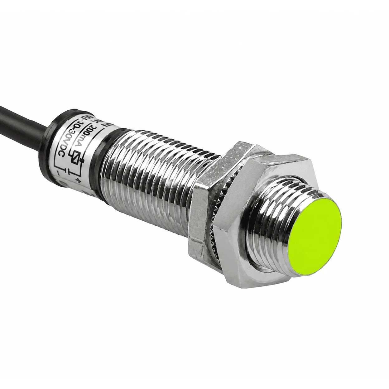
To find an equivalent inductive proximity sensor, identify the complete original model and compare its electrical interface, mounting, connection, and detection requirements with the proposed replacement. Then verify the candidate at the actual machine detection point. Matching the housing size and nominal sensing distance is a starting filter; it does not establish that the replacement will deliver the signal the machine needs.
Quick Answer: How Do You Find an Equivalent Inductive Proximity Sensor?
Use the original installation to build a requirement, then use the two datasheets to find differences. A practical search follows four steps:
- Identify the full original order code, wiring, target, and installed operating gap.
- Screen the candidate for electrical, mechanical, sensing, and environmental compatibility.
- Separate documented matches from unknown information and changes that would require engineering approval.
- Test the shortlisted device with the production target and receiving controller before accepting it for the machine.
An online cross-reference or supplier suggestion can provide a candidate for this process. Keep the comparison record and the machine test result together so that a recommended alternative is not mistaken for an already validated replacement.
Why Might Two Inductive Proximity Sensors Not Be Interchangeable?
Two sensors can detect metal using the same general principle yet interact differently with the machine. One may fit the bracket but drive the wrong input circuit. Another may match the output type but switch at a different point on a small target. Replacement depends on the complete detection function, from the metal feature through the sensor to the controller response.
Direct Replacement vs. Replacement Requiring Modifications
A direct replacement preserves the required installation and function without changing the machine's wiring, mounting arrangement, or control behavior. That judgment needs a defined scope: the particular detection point, target, input, operating conditions, and acceptance requirements.
An alternative that needs a new bracket, changed pin connections, a different input arrangement, or revised settings may still be worth evaluating. Treat it as a replacement requiring modifications. Record those changes and obtain the machine owner's engineering approval before implementation; do not describe it as a direct swap simply because the resulting system could be made to work.
Why Matching Thread Size and Sensing Distance Is Not Enough
A thread designation describes one mechanical interface. A nominal sensing distance describes a detection characteristic under stated reference conditions. Neither identifies the output current direction, switching function, body length, pin assignment, or effect of nearby mounting metal.
The question is therefore more specific than whether the candidate fits the hole and detects a steel plate. It is whether the candidate can occupy the required position, distinguish the intended target from its absence, and produce the correct input event throughout the machine's operating range.
Identify the Original Sensor Before Searching for a Replacement
Start with evidence of what is installed rather than a photograph of a similar product. A replacement search becomes much easier when the original device specification and the machine requirement are recorded separately. This also exposes an important possibility: the original sensor may have been operating with little margin, so reproducing its catalogue description alone may reproduce the problem.
Find the Manufacturer, Full Model Number, and Datasheet
Photograph the label and capture the complete order code, including suffixes and cable or connector options. Retain the original datasheet, installation drawing, wiring diagram, and any saved settings. A family name is useful for searching, but it may cover several outputs, connection variants, or mounting styles.
If the label is unreadable, look for the part number in the machine bill of materials, electrical drawings, purchase records, or spare-parts list. Use the physical dimensions and application to narrow the search, while keeping unresolved fields visible. Guessing the missing suffix can turn an apparently precise part number into the wrong device.
Record the Sensor's Function, Target Material, and Operating Gap
Describe what the machine must detect: a metal bracket reaching an end position, a tooth passing the sensing face, or a small feature on a moving part. Record the target material, dimensions, thickness, and approach direction. The whole part may be large even when the feature crossing the sensing face is small.
Measure or document the actual installed gap and its permitted variation. Include movement caused by fixtures, adjustment, vibration, and part tolerances. Record where the target must be detected and where the output must reset. These requirements are more useful than a note saying only “same sensing distance.”
Check the PLC Input, Wiring Diagram, and Existing Connection
Identify the actual receiving input channel, its common connection, and the sensor circuit feeding it. Record whether the machine uses a transistor switching output, a two-wire circuit, an analog signal, or IO-Link. Note any second output, diagnostic lead, junction box, or intermediate module.
Keep the sensor connection diagram and the cordset diagram together. A connector on the sensor may mate physically with the existing cable while its signal functions differ. The controller's programmed meaning also matters: target present, target absent, and loss of power must not be casually treated as equivalent states.
Match the Electrical Specifications First
Electrical screening should happen before a candidate is connected. A sensor that fits mechanically can still be unsuitable for the supply or receiving circuit. Compare the actual circuit requirements with the candidate's documented limits, rather than choosing from a single voltage or output label.
Supply Voltage, Current Consumption, and Load Rating
Check the supply type and permitted operating range, including relevant ripple or transient conditions in the device documentation. The voltage available at the sensor under normal machine load must remain within that range; a nominal supply label at the cabinet does not describe every condition at the device.
Separate the sensor's own current consumption from its allowable output load. The former contributes to supply loading; the latter describes what the output can drive under specified conditions. Compare on-state voltage drop and off-state leakage with the actual input's recognition and reset requirements. In an electronic two-wire circuit, the sensor and load share a current path, so these characteristics can determine whether the input turns on or releases correctly. [1]
PNP vs. NPN and Normally Open vs. Normally Closed
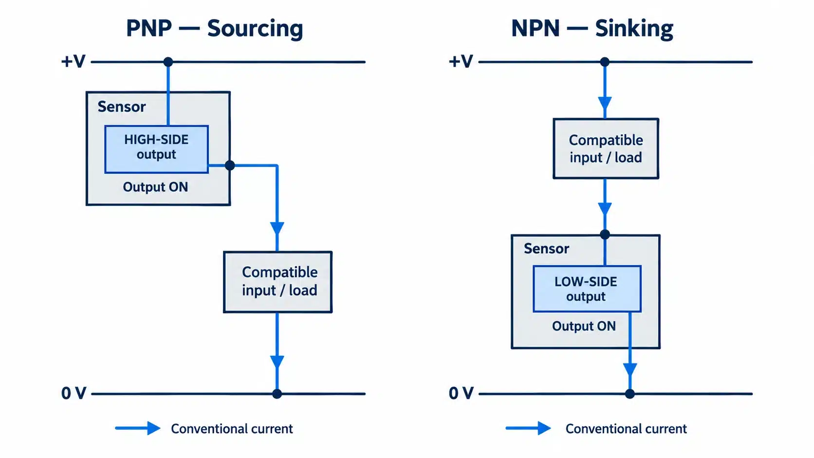
A PNP switching output typically supplies current to a load connected toward the negative supply reference. An NPN output typically sinks current from a load connected toward the positive supply. The receiving input must support the relevant circuit. Changing the software interpretation cannot create the missing current path. [2]
Normally open and normally closed describe a different property: how the output switching element responds to target presence. Compare target-present and target-absent behavior separately from PNP/NPN. Also check documented power-up, power-loss, and fault behavior where the machine relies on them. An NC label alone does not establish a safety function or guarantee that every wiring fault will be detected.
Two-Wire vs. Three-Wire vs. Four-Wire Sensor Connections
A two-wire electronic switch powers itself through its load circuit. A typical three-wire DC switching arrangement has separate supply connections and an output. Replacing one arrangement with the other requires a circuit comparison, not simply connecting a different number of conductors.
Four-wire devices can provide additional functions. One possible arrangement is two complementary switching outputs, NO and NC; an exact four-wire product example documents that configuration. It is not a rule for every four-wire sensor. Read the functions of each conductor or pin, including any unused output, before deciding whether the original harness can be retained. [3]
The number of cable cores, connector pins, and outputs actually used by the machine are separate facts. A four-pin connector does not, by itself, identify a four-wire electrical function.
NAMUR, Analog, and IO-Link Sensors Require Interface-Specific Checks
NAMUR devices use a current-signal interface intended for a suitable switch amplifier or receiving input. They cannot be grouped with ordinary two-wire switching sensors solely because two conductors are present. Keep the sensor, interface, and any application approvals within their documented system requirements. [4]
For an analog inductive device, compare the signal range, measurement behavior, scaling, and controller input. A switching output does not replace a continuous measured value merely because both devices detect metal.
For IO-Link, record the operating mode, device information, process-data interpretation, and application parameters. A replacement may have configurable switching functions or other settings that affect behavior. Retain the required device description and commissioning information; do not assume a common connector or an IO-Link label reproduces the old configuration. [5]
Verify the Mechanical Dimensions and Installation Requirements
After excluding incompatible electrical interfaces, compare the installation drawings. Mechanical equivalence means preserving the required sensing position and clearances as well as fitting the fastener. A replacement that forces the sensing face or cable into a different location changes the application being evaluated.
Housing Diameter, Thread Size, and Overall Length
Compare the thread specification, usable threaded length, overall body length, sensing-face position, and mounting hardware. A shorter body may not engage the existing bracket and nuts as intended. A longer body may interfere with moving equipment or leave insufficient room for a connector.
Check whether the housing can be held securely at the required gap using the specified tightening method and torque. Do not use the original nut position as a substitute for establishing the new sensing-face position. The drawing should support the fit before a trial installation is scheduled.
Flush vs. Non-Flush Mounting and Surrounding Metal Clearance
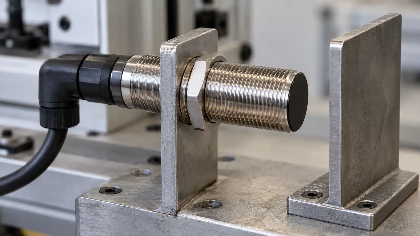
A sensor intended for flush mounting and one requiring non-flush installation interact differently with nearby metal. A non-flush candidate may screw into the same bracket while the metal around its active region violates its installation conditions. Surrounding metal can affect operation and reset, so this is a functional difference as well as a mounting detail. [1]
Compare side clearance, front-facing metal, recesses, adjacent sensors, and the permitted mounting arrangement on the exact drawing. If clearance cannot be achieved without changing the bracket or sensor position, record that as an installation modification. Use the existing inductive sensor mounting guide for the broader distinction, then return to the candidate's own dimensions.
Connector Type, Pinout, Cable Length, and Installation Space
Compare connector size and coding, pin count, pin function, and the cordset's actual conductor assignment. Include straight or angled exit direction, access for mating, and the room needed to avoid strain. A connector that can be screwed together is not proof that power and output reach the intended circuit points.
For a fixed cable, compare length, jacket suitability, permitted flexing, bend conditions, and routing. A replacement with a suitable housing but an unsuitable cable may fail at a moving or coolant-exposed installation. Keep any cable or connector adapter in the comparison record because it becomes part of the replacement system.
Compare Sensing Performance Under Real Operating Conditions
The candidate must detect the same required feature under the machine's conditions. Catalogue values help screen that question, but they must be interpreted using their reference target, mounting, and operating limits. A replacement decision should preserve a dependable difference between the target that must be detected and the condition that must not trigger the sensor.
Rated Sensing Distance vs. Reliable Operating Distance
Rated or nominal sensing distance provides a defined reference characteristic. The usable installed distance depends on the selected device's specifications and application conditions. Find the manufacturer's applicable operating or setting-distance information and compare it with the largest required gap, rather than positioning the target at the headline range and assuming margin remains. [6]
A longer-range candidate may provide useful margin in one installation but respond to unwanted metal in another. It can also alter where a moving feature switches or releases. Compare both required detection and unwanted actuation before treating increased range as an improvement.
Target Material, Size, Position, and Reduction Factors
The actual target may differ from the reference target used to specify the sensor. Material, feature size, thickness, curvature, and orientation can change the response. A small aluminum feature and a broad steel face should not be treated as interchangeable test objects.
Use correction factors or target-response data supplied for the selected sensor and their stated conditions. A material factor can help estimate a starting point, but it does not account automatically for every geometry or installation effect. Do not borrow a generic aluminum factor, multiply the nominal range, and call the result an assured production gap. Validate the real feature along its permitted path. [6]

Hysteresis, Repeatability, and Switching Frequency
Hysteresis describes the difference between operate and release positions. Repeatability concerns how consistently switching occurs under repeated, defined conditions. A replacement can switch reliably on approach yet require more withdrawal before it resets; that difference matters when targets or gaps are close together. [6]
Switching frequency and response time describe different aspects of behavior and use stated test methods. Compare the candidate's timing information with the shortest target-present and target-absent intervals, then include the receiving input's filtering or capture behavior. A higher catalogue frequency alone does not prove that the controller will count every production part. [7]
Temperature, IP Rating, Coolant Resistance, and Required Certifications
List what reaches the sensor, connector, and cable: temperature extremes, vibration, washdown, cutting fluids, oils, cleaning chemicals, or mechanical impacts. Compare the exact product documentation with those exposures. An ingress-protection code is one part of the specification; it is not a standalone compatibility statement for a particular coolant, chemical, or cable-flexing duty.
Where the machine requires a particular approval, verify the exact model and application scope using its current documentation. A series-level logo or another product's certificate does not establish coverage for the proposed unit. Safety-related and hazardous-area replacements require their own qualified system review; an ordinary workpiece sensor should not be selected as though it were a certified protective device. [1]
How to Use an Inductive Proximity Sensor Replacement Comparison Table
Use a single comparison record to turn the information above into a decision. Write the machine requirement in the original column where it is more restrictive than the old catalogue description. This prevents an old specification from silently replacing the application requirement.
Compare the Original and Candidate Sensor Specifications
For each row, record the actual value or function and its document reference. “Same,” “equivalent,” or a blank cell is not enough where the underlying requirement is still unknown.
| Comparison item | Original sensor or machine requirement | Candidate evidence to record | Decision affected |
|---|---|---|---|
| Supply and load | Supply type/range, input or load, relevant electrical limits | Operating range, consumption, output rating, leakage and voltage drop | Can the device operate and drive both intended states? |
| Output and function | PNP/NPN or other interface; NO/NC; additional functions used | Exact circuit, switching function and parameter requirements | Does the controller receive the required event? |
| Body and mounting | Thread, usable length, face position and bracket arrangement | Dimension drawing, mounting method and metal clearances | Is the original detection position retained? |
| Connection | Cordset, pin functions, cable requirements and available space | Connector/pin diagram, cable option and exit geometry | Can the existing connection be retained correctly? |
| Detection and timing | Target feature, gap range, approach, reset and machine speed | Applicable distance/target data, hysteresis and timing specifications | Is there sufficient present/absent and event-capture margin? |
| Environment and approval scope | Actual exposure and any required product/system approval | Exact-model environmental limits and applicable documents | Is the candidate suitable for the installed conditions? |
Classify the Result as Direct Match, Conditional Match, or Not Compatible
Use these as working categories for this comparison, not as certification terms:
- Direct Match: the documented candidate matches the defined requirements without functional installation changes. Keep its machine-validation status separate until testing is complete.
- Conditional Match: compatibility depends on a stated change or resolved condition, such as a revised bracket, approved wiring arrangement, or documented setting. Identify who must approve it and what must be retested.
- Not Compatible: a required characteristic conflicts with the proposed device in the installation being retained, or the needed modification is unacceptable.
Keep an unresolved status for decisive missing information. Unknown pin functions or an unverified usable gap cannot be promoted to Direct Match. A possible modification also should not be marked Conditional Match until a technically supported path has been identified.

Worked Example: Same M12 Housing and 4 mm Range, Different Output
Consider this hypothetical screening example. The original machine input is wired to receive current from a PNP sourcing sensor. A proposed alternative is described as M12 with a nominal 4 mm range, but it has an NPN sinking output. These are teaching assumptions, not specifications for an XSZ model or a verified pair of products.
| Selected field | Original requirement | Proposed candidate |
|---|---|---|
| Housing label | M12 | M12 |
| Nominal range label | 4 mm | 4 mm |
| Output current direction | PNP source, required by the existing input arrangement | NPN sink |
| Direct-swap screening result | Preserve the existing receiving circuit | Not compatible with that retained circuit |
The electrical mismatch is decisive before detection testing. The candidate output does not supply the current path the fixed receiving arrangement expects. Reversing NO/NC interpretation in software does not turn an NPN output into a PNP source. An interface change might be possible in a separately assessed design, but that would no longer be the direct replacement assumed here.
This example settles only one rejection criterion. It does not prove that two PNP devices with those same housing and range labels would be equivalent; mounting, connection, actual target behavior, and the remaining requirements would still need comparison.
How to Replace a Discontinued or Unavailable Sensor Model
When a part is unavailable, preserve its technical requirement before searching more broadly. The objective is to retain the machine function with documented compatibility, rather than to find the closest-looking item that can be purchased immediately.
Search Using the Full Model Number and Key Specifications
Start with the original manufacturer's product record, discontinuation notice, and recommended-successor information. Search the complete order code, then use the documented electrical, mounting, connection, and target requirements to investigate alternatives.
A successor listing deserves close reading. An original manufacturer discontinuation notice can identify changed characteristics and even list some codes with no recommended replacement. Its recommendation is a starting document for comparison, not evidence that every detail is unchanged. [8]
Evaluate Cross-Brand Alternatives Without Assuming Interchangeability
Ask for the exact proposed order code and its datasheet, drawing, wiring, and relevant installation limits. Compare those documents against the same machine requirement used for the original. A broad cross-reference list may narrow the search without revealing every connection, cable, or application difference.
Request a written explanation of deviations when a supplier proposes an alternative. For the inductive proximity sensor family, the useful question is which documented configuration fits the particular detection point. A family name alone cannot establish that conclusion.
What to Do When No Exact Replacement Is Available
First determine whether the obstacle is missing evidence or a confirmed incompatibility. An absent pin diagram calls for documentation; a body that cannot occupy the required space is a different problem. Keep those findings separate so that the next search addresses the actual constraint.
If retaining the original interface and installation is impossible, define the proposed mechanical, electrical, or control changes as an engineering change. The machine's responsible party must decide whether to accept that scope and its verification requirements. Do not force an unsuitable sensor into the old position or conceal a design change inside an “equivalent” purchase description.
How to Test an Equivalent Sensor Before Full Replacement
Testing confirms whether a documented candidate performs the intended detection task. Plan the observations before installing it so that a lit indicator or one successful cycle is not mistaken for complete acceptance.
Verify Wiring, Voltage, and Both Switching States
Use qualified personnel and the machine's approved maintenance and energy-isolation procedure for removal, mounting, and connection. Disconnect the sensor supply before connection work and follow the selected product's instructions; manufacturer installation guidance explicitly separates that work from applying power. [5]
After the circuit has been checked and safely commissioned, verify the supply at the sensor under the relevant load and observe target-present and target-absent behavior. Compare the electrical output with the intended PLC input and programmed event. Confirm any second output or diagnostic function actually used. The proximity-switch testing guide provides a broader test sequence; the replacement record should retain the observations specific to this candidate.
Test Minimum and Maximum Detection Gaps and Worst-Case Targets
Use representative production parts, including the smallest or least favorable feature within the approved application. Test both ends of the allowed gap and position range, using the final mounting metal and target path. Confirm that the sensor detects what it should and remains inactive for the intended absent condition.
Measure or record operate and release positions when they affect the machine function. Include the movement needed to reset before the next event. If a candidate detects the target only at a conveniently adjusted position, the result does not establish suitability across the required tolerance range.
Check Machine Speed, Environmental Conditions, and Long-Term Stability
Repeat the checks at the relevant machine speed, with the normal target spacing and receiving-input settings. Compare the reference part count or machine events with the actual input/program result. A slow manual pass cannot establish that the shortest production pulses will be captured.
Plan observation across representative duty cycles and relevant changes such as warm-up, vibration, part variation, and expected exposure. The application owner should define the test duration, sample coverage, and acceptance criteria according to risk and service conditions. Record missed or unwanted transitions, shifts in switching behavior, and any test limitation. A short clean run is evidence about that run, not a demonstrated lifetime result.
What Information Should You Provide to Find a Replacement Sensor?
A useful replacement request allows the recipient to compare the real requirement rather than infer it. Send the original information and the machine conditions together, then ask the supplier to identify any exceptions in its recommendation.
Original Model Number, Label Photo, and Datasheet
Provide the manufacturer, complete order code, clear label photographs, and the original datasheet and connection drawing. Add the reason for replacement: damage, intermittent behavior, obsolescence, or supply availability. If information is missing, state which fields could not be recovered instead of presenting an incomplete code as certain.
Required Electrical, Mechanical, and Detection Specifications
Include the receiving input/module and wiring, output function, supply conditions, mounting drawing or photographs, connection details, target material and feature dimensions, installed gap range, movement, and machine speed. Identify environmental exposure and any required approval scope. Attach the comparison matrix and the acceptance observations that the candidate must satisfy.
Quantity, Application, and Any OEM Customization Requirements
State the sample quantity, expected production demand, replacement schedule, and any requested cable, connector, or mounting variation. Separate mandatory requirements from preferences so that a supplier can explain which differences are technically acceptable and which require a change.
When contacting xsz sensor about a customized model requirement, include the original device and the unresolved compatibility points. Request a defined candidate configuration, supporting documents, and an agreed validation plan. Treat feasibility, availability, and acceptance as items to confirm for that request rather than assumptions carried over from a similar product.
Frequently Asked Questions About Inductive Sensor Replacements
Can I Replace an Inductive Proximity Sensor with Another Brand?
Yes, a different brand can be evaluated as a replacement. Compare the exact candidate with the application requirements and verify it on the machine. Brand identity neither establishes nor rules out compatibility; an unsupported cross-reference should remain a candidate, not an accepted equivalent.
Can a PNP Sensor Replace an NPN Sensor?
Not as a direct swap into a fixed circuit that requires the original current direction. Some systems may permit a properly assessed input or interface change, but that is a modification requiring the relevant engineering review. Changing NO/NC interpretation alone does not resolve PNP/NPN compatibility.
Can I Use a Sensor with a Longer Sensing Distance?
Possibly, if its documented mounting and target behavior preserve the required present/absent distinction and switching/reset positions. Check nearby metal and the actual target path. Additional nominal range is not automatically additional usable margin in the existing installation.
Are Flush and Non-Flush Inductive Sensors Interchangeable?
Only when the candidate's installation requirements can be met and its application behavior is verified. A non-flush sensor inserted into a bracket intended for a flush device may face unsuitable surrounding metal. If a bracket or position change is required, classify and assess that modification explicitly.
What If the Original Sensor Model Is Discontinued?
Recover the full original specification, read the manufacturer's successor or discontinuation information, and compare any recommended or cross-brand candidate against the same machine requirement. When no suitable direct replacement is established, document the missing information or required design changes before ordering a substitute.
Technical References
- OMRON — Proximity Sensor Safety Precautions
- OMRON — NPN and PNP Sensor Outputs, FAQ00379
- Pepperl+Fuchs — NCB50-FP-A2-P4-BHMSP4 Datasheet, 26 March 2026
- Pepperl+Fuchs — NAMUR Output Sensor Fundamentals, 18 September 2026
- Pepperl+Fuchs — Reduction Factor 1 Sensors with IO-Link Manual, August 2018
- Baumer — Working Principle and Technology of Inductive Sensors
- OMRON — Proximity Sensor Terminology
- OMRON — Partial E2E Series Discontinuation Notice, OMSQ-C(02)218096, 30 September 2022