
How to Choose a Rectangular Photoelectric Sensor
Choose a rectangular photoelectric sensor by matching its sensing method to the target and the available light path, then checking the working distance, complete mounting space, electrical output and timing. Confirm the choice with representative targets in the intended installation. The rectangular housing tells you how the sensor is packaged; it does not establish which objects it can detect or how reliably it will work.
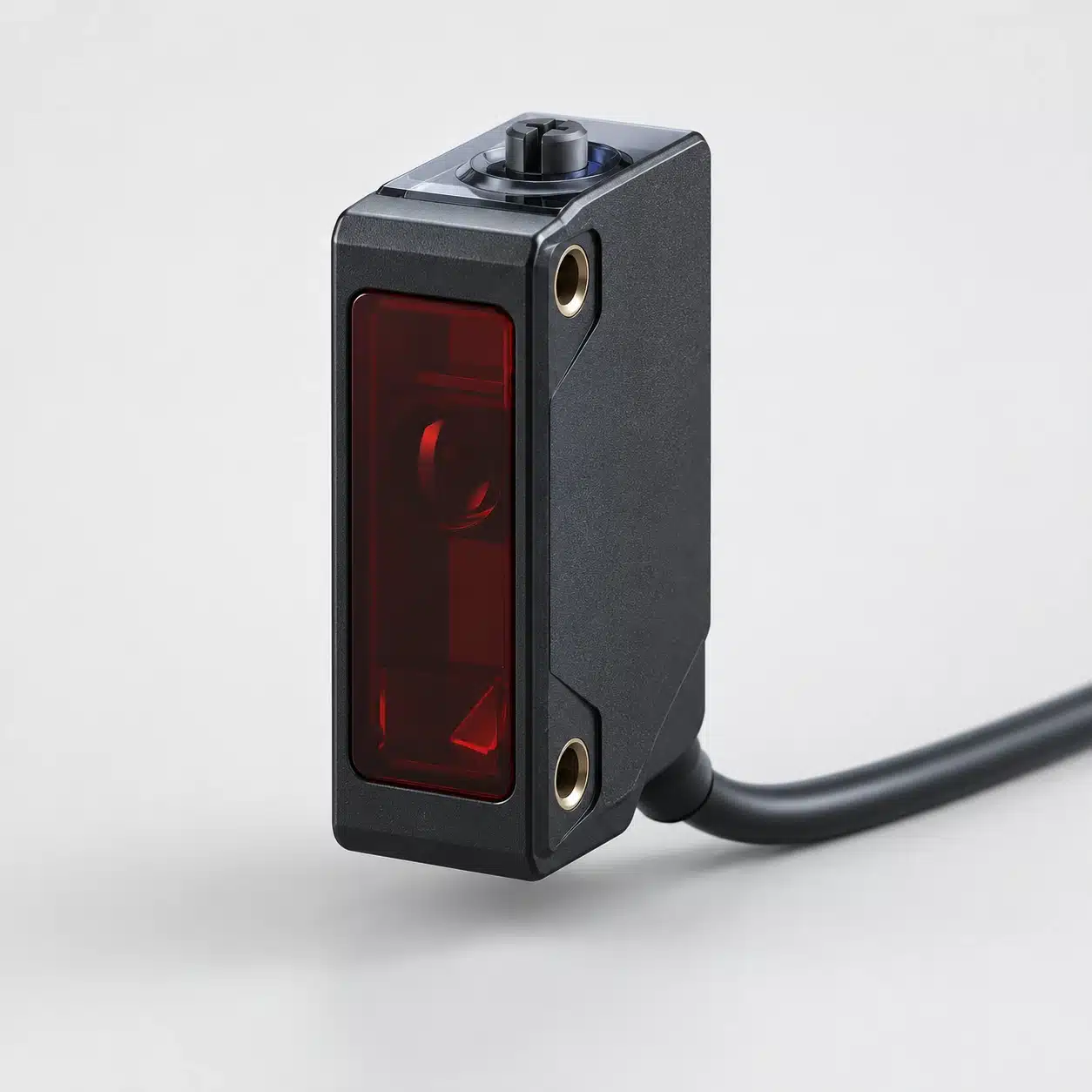
Start with the two conditions your machine must distinguish. Detecting a carton against an empty conveyor, detecting a clear container and checking a small feature are different optical tasks, even if the available mounting space looks similar. A useful selection process connects that task to the sensor configuration before comparing catalogue dimensions or maximum range.
Quick Selection Guide: What to Confirm First
Use these checks to screen candidates. The table identifies what needs confirmation, rather than assigning specifications to every rectangular sensor.
| Selection check | What to confirm | Why it changes the choice |
|---|---|---|
| Detection task and target | Required feature, material, surface, position variation, and acceptable and unacceptable states | Defines the optical difference the sensor must recognize |
| Optical arrangement | Access for an opposing receiver or reflector, or a requirement for sensing from one side | Determines which sensing methods can fit the detection point |
| Working distance and margin | Actual target path, reference target or reflector, near limit and documented operating range | Prevents a headline range from being treated as an application guarantee |
| Complete mounted envelope | Body, optical axis, mounting holes, bracket, connector, cable and adjustment access | Checks whether the working assembly fits, not just the housing |
| Output and supply | Exact supply, output circuit, receiving input and Light-ON/Dark-ON setting | Establishes electrical compatibility and the required output state |
| Timing and target spacing | Shortest target and gap intervals, sensor on/off response and receiving-input requirements | Checks whether both states can be recognized at operating speed |
| Environment and acceptance | Lighting, contamination, temperature, cleaning exposure and representative test conditions | Turns a catalogue shortlist into a candidate that can be evaluated for the installation |
Choose the Sensing Method for the Detection Task
The first decision is where the useful light signal comes from. Once that is clear, the rectangular package becomes a mechanical choice within a suitable optical arrangement.
Through-Beam and Retroreflective Arrangements
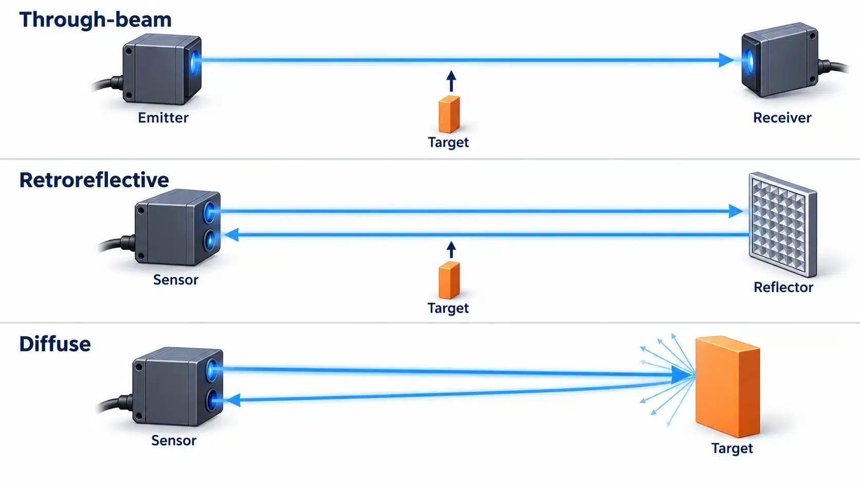
A through-beam arrangement places an emitter and receiver on opposite sides of the detection path. A suitable target is detected by interrupting the beam. Retroreflective sensing places the emitter and receiver in one housing and uses a reflector opposite it; the target interrupts the returning path. Diffuse sensing, discussed below, instead uses light returned by the target itself.
For an opaque part with varying surface colours, consider whether a beam-interruption arrangement is practical before trying to make every surface return a similar signal. This is a starting point for selection, not proof that any part will block enough light. Check the smallest required feature and its full permitted path against the candidate's documented detection conditions.
The mounting trade-off is concrete. A through-beam candidate needs space and wiring access for the opposite unit. A retroreflective candidate still needs room for the specified reflector and its alignment. Mark both ends of the path on the machine drawing. A sensor that fits the near side is not a complete solution if a guard, changeover mechanism or product guide occupies the far-side position.
Diffuse Sensing and Background Suppression
Diffuse sensing is often a useful starting point when only one-sided access is available. However, the target and the background become part of the optical assessment. If the sensor responds to the target but also responds to the surface behind it, detection alone has not solved the task: the machine still cannot distinguish presence from absence.
Background suppression (BGS) uses distance discrimination to help separate a nearer target from a farther background. It does not make every surface or separation suitable. Check the candidate's specified sensing and cutoff conditions with the real target, including the closest background position.
If the target and background cannot be separated consistently, reconsider their positions or the optical method rather than relying only on repeated sensitivity adjustments. During selection, record which physical change would make the two states easier to distinguish. That gives the machine designer an actionable alternative when a preferred mounting position proves unsuitable.
Check the Target, Working Distance and Optical Margin
A model should be evaluated against the part that matters to the process. A large, easy-to-detect surface can conceal a problem with the smaller feature that actually determines whether the machine should act.
Target Size, Surface and Background
Describe the required feature separately from the overall product. For a component on a carrier, for example, the question may be whether the component is present, not whether the carrier has arrived. Treat the empty carrier as a rejection sample. Otherwise, a successful trial may simply show that the sensor can detect the carrier in both conditions.
For diffuse candidates, surface colour, finish and angle can change the received signal. Put the actual variation into the sample set: different finishes or labels, permitted tilt, and the nearest and farthest positions. Then repeat the check with the target removed. This makes a background response visible before it becomes an installation problem.
Transparent objects deserve a separate suitability check. Their shape can alter the light path; a clear container can produce missed or multiple responses under some optical conditions. A rectangular shape or a general photoelectric label is not evidence of transparent-object capability. Ask for an appropriate model and test the actual container shape, orientation and spacing rather than substituting an opaque sample.
Keep the acceptance question precise: does each permitted target condition produce the required state, and does each permitted no-target condition produce the other state? This is more useful than asking whether the sensor can detect a sample at least once.
Rated Range, Blind Zones and Detection Margin
Read the reference conditions beside the distance specification. Diffuse range may be stated using a standard white target; retroreflective range can depend on the specified reflector. A near dead zone or minimum operating distance may also matter. Do not treat maximum range as a complete description of the usable installation distance.
Optical margin describes how much useful signal is available beyond the switching threshold. Excess gain is one way of expressing that relationship. Contamination can attenuate light, and published curves have stated test conditions. More gain is not an unconditional improvement if it makes the target and no-target states harder to distinguish.
For a shortlist, write down the actual distance range caused by product movement and mounting tolerances. Compare it with the candidate's applicable data, then test the ends of that range. If the only successful setting is a narrow position that the machine cannot maintain, reconsider the arrangement. Do not assign an arbitrary percentage of catalogue range as a universal safe working distance.
Where the documentation leaves a decisive condition unclear, request the relevant curve or application clarification. A larger range number is not a substitute for that missing information.
Check the Complete Installation Space
The useful mechanical comparison is the installed assembly. A body outline alone leaves out the parts that can prevent alignment, cable connection or later adjustment.
Housing Dimensions, Beam Axis and Mounting
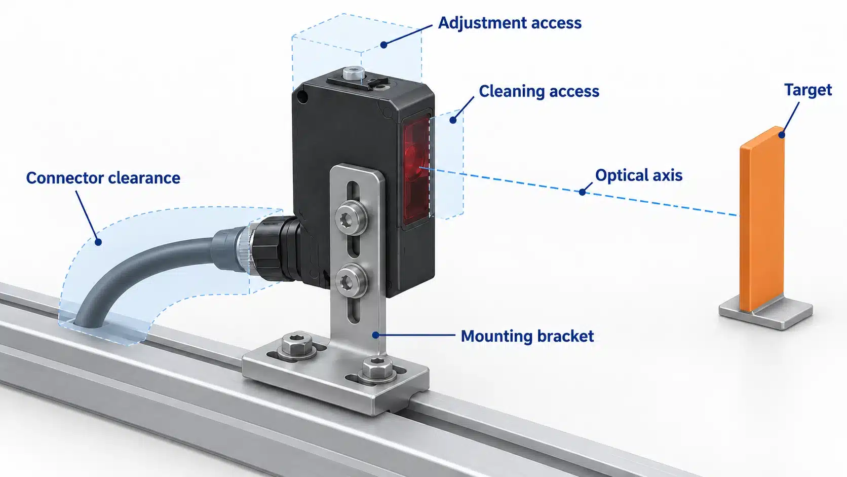
Use the exact model drawing to locate the optical axis relative to the mounting holes and reference surfaces. Then place that axis at the required detection point on the machine drawing. Work outward to check the housing and bracket clearance. This sequence avoids selecting a convenient bolt pattern and discovering later that the beam misses the feature.
Check the permitted adjustment range as well as the final position. A bracket may need room to move during alignment, and its fasteners must remain accessible. Include nearby guards, moving assemblies and the product's full travel envelope in the fit check. Follow the manufacturer's mounting instructions rather than assuming that a similar-looking housing accepts the same fastening method.
When replacing a unit, compare the new drawing with the installed reference position. Matching external dimensions does not establish matching optical-axis location, mounting details or configuration. Record what can remain unchanged and what must be repositioned before accepting a replacement.
Reflectors, Receivers, Cables and Adjustment Access
Add the reflector or receiver to the installation drawing where the selected method requires one. Include its mounting and alignment space, and identify how it will be reached for inspection. An arrangement that can be aligned only before the rest of the machine is assembled may be difficult to maintain.
For the sensor connection, check the actual connector and cordset or cable-exit arrangement. Include the documented bend allowance and the space needed to connect or remove it. A right-angle and a straight connection can require different clearances; choose from documented compatible options rather than assuming they are interchangeable.
Finally, identify how someone will view the indicator, reach a sensitivity or teach control where fitted, and clean the optical surfaces. These checks do not rank one housing shape above another. They establish whether the selected rectangular assembly can be installed and serviced at this particular point.
Match the Output and Timing to the Control System
Finish the shortlist at the receiving device. Optical suitability does not establish electrical compatibility, and a familiar family name does not identify the complete configuration.
Supply, Output Circuit and Switching Logic
Check the full ordering code and its wiring documentation. Rectangular families can include different supply and output variants, including transistor or relay outputs. Do not infer supply voltage, load rating or response from the case shape or from another member of the family.
For a transistor output, confirm the NPN or PNP configuration against the actual receiving input. For a relay output, check the documented contact arrangement, permitted load and switching requirements. In either case, compare the sensor specification with the input or load specification; a product label alone is insufficient to confirm a match.
Light-ON and Dark-ON describe operation relative to received light. They are a separate choice from the output circuit. Define the wanted machine signal in plain language, such as “input active when the target is present,” then use the selected sensing method and model's truth table to choose the setting.
Include the exact connection diagram in the selection record. Do not copy wire colours or connector pin assignments from an unrelated model. Make electrical connections under the equipment's approved isolation procedure and the applicable sensor and controller instructions.
Response Time and the Receiving Input
Response time is the delay between an optical change and the output operating or resetting. Check both transitions. For repeated parts, the receiving system needs to recognize the target condition and the intervening gap; an acceptable response in one direction does not establish the complete sequence.
Record the shortest required target and gap intervals at the intended speed, including the product spacing variation allowed by the process. Compare those requirements with the candidate's documented timing and with the receiving input's specifications and settings. Keep filter, capture or counting settings with the record where they apply.
A practical acceptance check observes the result at the controller as well as the sensor. The indicator is useful for diagnosis, but it is not the acceptance record for a counting or control function. Check that the installed system recognizes the required sequence without missed or additional events under the agreed conditions. Do not convert a catalogue headline into an allowed machine rate without confirming how it was specified and how the input operates.
Validate the Installation Before Ordering
Use the shortlist to organize a controlled application check. The purpose is to establish whether a candidate meets the defined task within its documented limits, and to make any unresolved condition visible before an order is placed.
Test Representative Targets and Operating Conditions
Agree on expected results before adjusting the sensor. For presence detection, define which target and no-target conditions must be distinguished. For counting, establish an independent reference count. For feature detection, retain acceptable and unacceptable samples that represent the actual decision.
- Assemble the candidate sensor, required accessories and receiving input in the proposed geometry. Record the exact model codes and settings.
- Check representative target variations and permitted positions, including the boundary conditions that are hardest to distinguish. Confirm the corresponding no-target or unacceptable states as well.
- Run the relevant target and gap sequence at the intended operating conditions. Observe the receiving system's result, not only the local indicator.
- Evaluate the foreseeable lighting, contamination and mechanical conditions against the sensor's documented limits. Use a safe, agreed method; do not expose equipment to conditions beyond its rating to imitate a test.
- Record the setup, samples, expected results, observed results and unresolved exceptions. Change one relevant condition at a time when investigating a failure, then repeat the affected checks.
Environmental suitability also needs documentation. Check temperature, moisture or condensation restrictions, cleaning exposure and housing or cable compatibility where relevant. Do not substitute a general protection label for the manufacturer's conditions for the actual exposure.
If a candidate works only after excluding a normal production variation, either change that process condition deliberately or reconsider the candidate. A successful demonstration under easier conditions does not resolve the original requirement.
Prepare the Information Needed for Model Selection
A useful enquiry lets a supplier understand the detection point without guessing. Send a compact selection package containing:
- Photos or a drawing showing the detection point, target path, background and available mounting positions.
- Representative target details or samples, including the smallest required feature, surface variations and the states that must be rejected.
- The installation drawing with distance limits, mounting references and space for accessories, connections and adjustment.
- The supply and receiving-device details, required output state, operating sequence and relevant input settings.
- Environmental and cleaning conditions, together with the test record and any unresolved exceptions.
Ask the supplier to identify the exact proposed configuration, required accessories, applicable documentation and any conditions still requiring validation. For an XSZ selection enquiry, use the same package to explain the application; confirm performance against the proposed model's own data and the agreed sample checks. The outcome should be a documented candidate and a clear acceptance basis, not a selection made from housing appearance alone.
Technical Sources
- OMRON — Photoelectric Sensors: Introduction. Sensing arrangements and target/background considerations.
- OMRON — Photoelectric Sensors: Explanation of Terms. Distance, dead-zone, response and operating-logic definitions.
- Banner Engineering — What Is Excess Gain and How to Use It to Choose a Sensor. Optical margin, contamination and the conditions behind gain guidance.
- OMRON — E3JK Specifications. Published variant tables illustrating why supply, output, accessories and conditions must be checked by model; last updated October 28, 2015. These are not XSZ specifications.
- Banner Engineering — Photoelectric Sensors. Housing style and sensing method as separate selection attributes.
- OMRON Europe — E3Z-B. Transparent-object sensing considerations and model-specific configurations.