
How to Choose a Capacitive Proximity Sensor for Material or Level Detection
Choose a capacitive proximity sensor by testing whether it reliably separates the required material-present state from the empty or unwanted state in the final mounting arrangement. Start with the actual material, working gap and container wall, then confirm adjustment, process exposure and controller compatibility. A material name or headline sensing distance is not enough to establish suitability.
Quick Selection: Define What Must Change the Signal
First describe the event the machine needs to recognize. Detecting a plastic component means distinguishing that component from the space around it. Detecting a level point through a vessel wall means distinguishing material at that location from the wall without that material. Those are different tests, even when both use capacitive sensing.
Use the following guide to prepare a candidate evaluation. These are conditions to verify, not guaranteed specifications.
| Selection condition | What to verify |
|---|---|
| Required event | Material presence or a specified level point; define what counts as absent. |
| Actual material | Composition, solid/liquid/bulk form, sample size and expected variation. |
| Wall or barrier | Material, thickness, layers, sensor-to-wall gap and response to the empty wall. |
| Working geometry | Required gap, target coverage and permitted changes in position. |
| Mounting and exposure | Flush/non-flush requirements, surrounding materials, temperature, chemicals and cleaning. |
| Adjustment and interference | Separation of both states at one setup, including relevant residue, foam or condensation. |
| Output and timing | Exact supply, output circuit, switching logic, connection and receiving-input requirements. |
A switching proximity sensor indicates a defined state. It does not automatically report continuous fill height. If the process needs a changing level measurement rather than a signal at one location, specify that requirement before choosing the product configuration.
Evaluate the Actual Material, Not Just Its Name
Dielectric Response, Target Size, and Working Gap
A capacitive sensor responds to a change in capacitance associated with its electric field. Material entering that field changes the electrical condition evaluated by the sensor. The resulting response depends on both the material's electrical properties and how much of it occupies the relevant sensing region.
Dielectric response describes how the material affects the electric field. It helps explain why different materials produce different responses, but a dielectric-value chart cannot select a model by itself. Target size, shape and distance also affect detection. A large sample covering the sensing area does not establish the same usable gap for a narrow component or a smaller amount of material.
For material-presence detection, test the least favorable permitted position, not just a sample held close to the face. Ask whether the sensor can still distinguish the target when it is smallest, farthest away or least well aligned within the actual positioning tolerance. That is the gap the machine must accommodate.
Also establish what the quoted sensing distance means. Some manufacturer ratings use a defined reference target and mounting condition; Pepperl+Fuchs, for example, describes a grounded metal reference target in its capacitive-sensor catalogue. Such a rating is not a promise of identical range on a plastic part, powder or liquid behind a wall. Use the selected model's definitions and actual samples to establish a usable working arrangement.
Moisture and Material Variation
The material tested during commissioning should represent the material used in production. A change in composition or moisture can change the capacitive response, so a setup accepted with one convenient sample may not cover the full process.
Identify the variation that matters for this application. For a bulk material, that might include its actual form and moisture range. For a liquid, it might include different permitted formulations. Record those variations as test conditions instead of treating every product with the same general name as equivalent.
The practical question is whether one intended setup still separates the required states across that variation. Raising sensitivity may recover a weak target, but it can also make unwanted surrounding material easier to detect. Evaluate both effects together; a stronger indication on one sample alone does not establish a better selection.
Choose Direct Detection or Through-Wall Level Detection
Direct Detection and Media-Contact Limits
In direct material detection, the sensor evaluates the target without a container wall between its sensing face and the target. This can simplify the sensing geometry, but the mounting must still keep the required target within the usable field and unwanted materials outside its influence.
Direct detection does not necessarily require physical contact. A nearby moving component can be detected across a gap. A level arrangement that exposes a sensor face to the medium is a separate mechanical and compatibility decision: the exact device must be suitable for that contact and for the process conditions. A generic proximity-switch description is insufficient permission to immerse it or install it as a process fitting.
Do not assume an ordinary external capacitive proximity sensor will detect contents through an intact metal tank wall. Depending on the process, a suitable access point, nonconductive window, bypass arrangement or another sensing approach may be needed. Choosing access first avoids trying to solve an unsuitable barrier merely by increasing sensitivity.
Sensing Through a Non-Metallic Container Wall
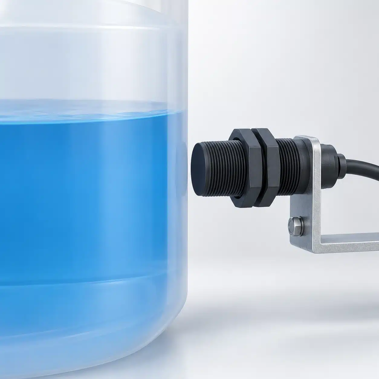
Suitable capacitive arrangements can detect material through an electrically nonconductive wall. The sensor remains outside while the material changes the electrical condition at the sensing location. However, the wall also contributes to what the sensor sees; the selection problem is to identify the added effect of the contents.
Test the complete assembly: actual wall material, thickness, layers, curvature, mounting position and sensor-to-wall spacing. A loose sensor held against a spare sheet is only an initial check if the production installation has a different wall or gap. There is no universal wall-thickness allowance that establishes suitability for every sensor and material.
For a point-level application, check the wall with material at the intended location and with material below it. If the empty wall already produces the required output, the setup has not demonstrated level discrimination. If reducing sensitivity then loses the filled condition, the available settings may not separate the two states. Change the arrangement or evaluate another candidate rather than accepting an unstable compromise.

Check Mounting, Nearby Materials, and Process Exposure
Flush or Non-Flush Mounting and Required Clearance
Capacitive sensing is influenced by material around the sensing region as well as the intended target. A bracket, adjacent wall or nearby stored material can therefore change the conditions established during a free-air test. Final mounting belongs in the selection test, not just in the installation drawing prepared afterward.
Flush and non-flush mounting are model-specific requirements. Follow the selected device's drawing for face position, surrounding material and clear zones; do not transfer dimensions from a similar-looking housing. A sensor that fits a hole mechanically is not necessarily suitable for that mounting electrically.
Make a sketch showing the sensor, target or vessel, brackets and nearby structures. Repeat the sensing check with those parts installed. If moving an adjacent item changes the output while the intended target stays unchanged, investigate that influence before locking the adjustment. The machine needs to recognize the target, not an accidental mounting condition.
Housing Compatibility, Temperature, and Cleaning
Separate detection feasibility from service suitability. A sample test can show that a candidate distinguishes two states; it cannot establish resistance to a cleaning chemical or suitability for prolonged process exposure.
List the temperatures the sensor will encounter and the substances that can reach the housing, sensing face, cable and connector. Include the cleaning method and whether deposits remain afterward. Obtain compatibility and operating limits for the exact variant rather than assuming that a housing material or family description covers every chemical and cleaning condition.
When media contact is proposed, check it explicitly with the supplier. For external mounting, check exposure from spills, washing and condensation. If the required environment has not been established in the product documentation, treat suitability as unresolved even when the initial switching test looks satisfactory.
Choose Adjustment That Separates Material From Interference
Set Up With Both Present and Absent States
Adjustment should establish useful discrimination, not simply make the indicator turn on. The sensor must recognize the required material and reject the relevant unwanted state using the same intended setup.
Use the adjustment method documented for the selected model. Capacitive families differ: an adjustable setting, teach procedure or fixed configuration cannot be assumed from the general technology name. There is no universal turn count, adjustment direction or sensitivity percentage for commissioning.
For an external level point, establish the empty-wall response, introduce material at the required location and check both transitions. Then repeat without changing the setup. For direct presence detection, use the actual target and the surrounding machine without that target. A setting that works only after retuning for each state is not an accepted selection.
If adjustment offers no dependable distinction, identify what overlaps: a weak target signal, a strong wall response or changing surroundings. This directs the next action toward gap, position, mounting or a different sensor configuration. Maximum sensitivity is not a substitute for a distinguishable sensing condition.
Residue, Foam, and Condensation Need Their Own Check
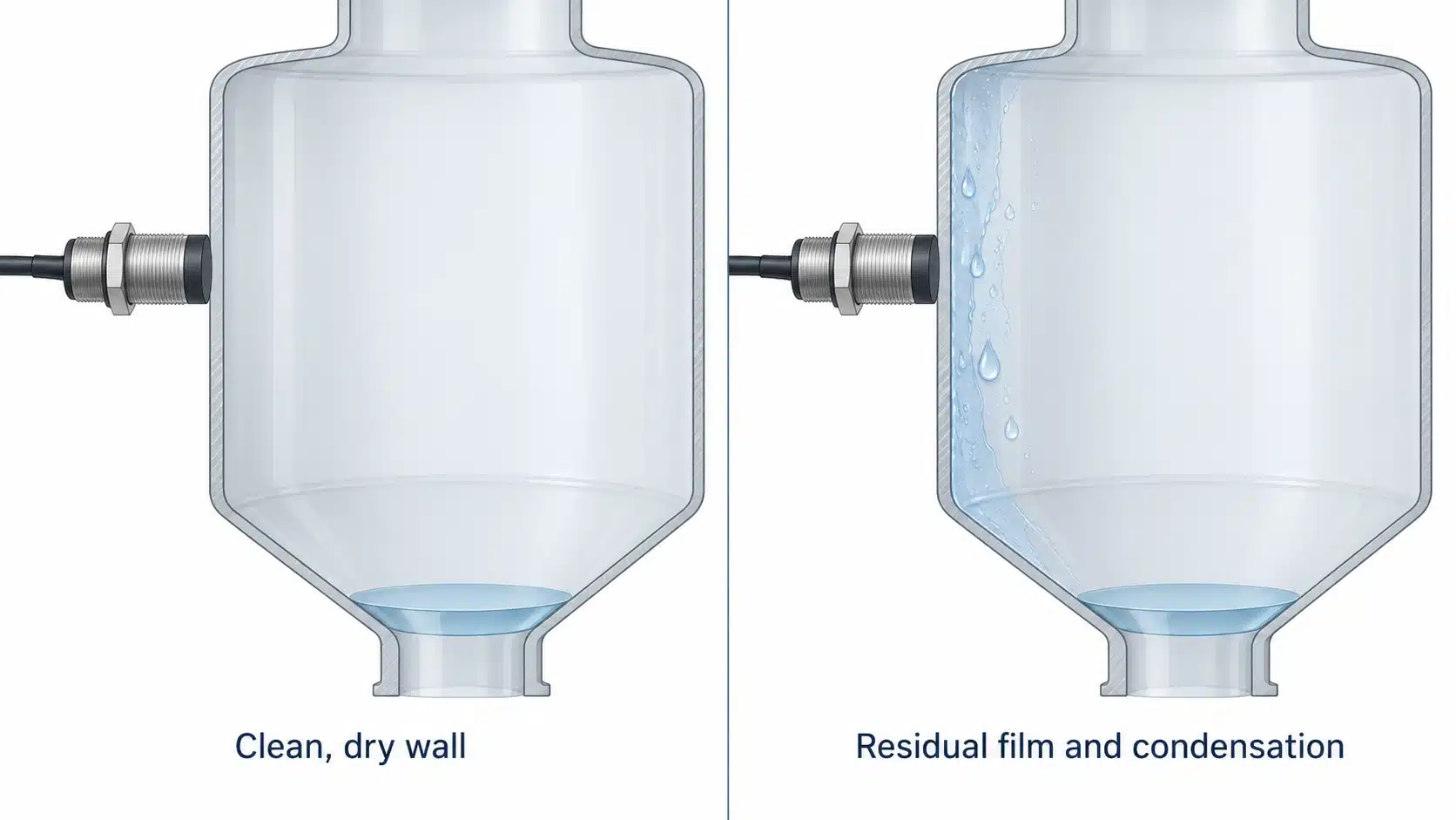
An empty vessel need not be electrically equivalent to a clean, dry vessel. Adhering material, condensation or foam can affect the response at the sensing location. Decide which of these should count as material present and which must be rejected for the process to work.
For example, suppose the required signal means bulk liquid has reached a point, while a wet wall after draining should count as empty. A clean-container test does not answer that question. Repeat the absent-state test with representative wetting or residue, then verify that the required filled condition remains detectable at the same setup. This is an application test to perform, not a report of measured XSZ performance.
Some devices provide dedicated functions for particular interference conditions. Confirm the exact feature, medium and limits before relying on it. Do not infer automatic compensation or immunity from the word capacitive. Where buildup cannot be rejected reliably, reconsider the sensing position, maintenance arrangement or sensing method.
Match the Output to the Controller
Supply, NPN/PNP, and NO/NC
After establishing a viable sensing arrangement, check the exact ordering variant against the electrical installation. Confirm supply type and range, output circuit, load requirements and connection drawing. Similar housings or related model suffixes do not establish electrical interchangeability.
In common three-wire DC transistor circuits, an NPN output switches current toward supply negative, with the load connected toward positive. A PNP output supplies current toward the load, which returns toward negative. The receiving input must support the corresponding circuit. Use the sensor and input diagrams together; this distinction is not a universal wiring instruction for every capacitive device.
Normally open (NO) and normally closed (NC) describe switching behavior and are separate from NPN/PNP. Write down which electrical input state should mean material present, then verify both present and absent states at the controller. A correctly changing sensor indicator does not by itself establish that the receiving input has recognized the intended condition.
Switching Response and the Required Process Event
A slowly changing vessel level and a brief passing component impose different timing requirements. Define how long the required condition exists and how quickly the machine must recognize its appearance and disappearance.
Check the selected sensor's switching-response limits and the controller input's filtering and capture behavior. A quoted switching-frequency figure alone does not establish that a short event will be recognized by the complete chain. Verify the transition at the receiving input under the intended process timing, including return to the absent state.
This is especially useful when a static bench test passes but the application involves motion or short material intervals. Record both electrical compatibility and observed event recognition; neither substitutes for the other.
Validate the Candidate and Prepare the Supplier Brief
Test the Weakest Material Signal and Strongest Empty-State Interference
Use a qualification test that challenges the proposed distinction. Select representative conditions from the actual process rather than assigning an arbitrary universal test gap or number of cycles.
- Assemble the intended sensor, mounting parts, wall or target path, supply and receiving input. Define the required output for both states before testing.
- Test the weakest required present condition: relevant material variation, least target coverage or largest permitted gap. For a level point, place material at the required sensing location.
- Test the strongest unwanted absent condition: the empty assembly with relevant surrounding material, residue, moisture or foam that the process must reject.
- Alternate between those conditions at the same intended setup. Include filling/draining or target motion as appropriate, and verify both states at the receiving input.
- Agree the required repeatability, event timing and acceptance criteria with the application owner. Record failures and unresolved conditions rather than retuning between tests to obtain isolated successes.
These steps are a recommended application qualification approach, not a certified protection test or a guarantee for every process. If the required and unwanted conditions cannot be distinguished, return to geometry, access and sensor configuration before ordering. A successful clean-sample demonstration should not overrule a failed production-relevant condition.
Record the Accepted Setup Before Ordering
Give the supplier enough information to evaluate an exact candidate rather than requesting a sensor for plastic or liquid in general. Include:
- The material and representative samples, expected variation, and the event to detect.
- A drawing or photographs of the target path or vessel wall, with material, thickness, layers, gaps and nearby structures identified.
- The required position tolerance, detection point, process timing, temperature and cleaning or chemical exposure.
- Supply, receiving-input details, required output circuit and switching behavior, plus cable or connector requirements.
- The candidate ordering code, adjustment record, test conditions, acceptance criteria and any unresolved result.
Keep that record with the final installation so a replacement or process change can be evaluated against the accepted arrangement. Sample testing supports the conditions actually checked; it does not establish untested material or environmental limits.
For XSZ's relevant product family, see capacitive proximity sensors. Share the material, wall and mounting details together with electrical requirements when discussing a candidate. Confirm exact-model documentation and a representative sample test before treating it as suitable for the detection point.
Technical Sources
- Pepperl+Fuchs — Capacitive Sensors, Introduction: sensing principle, reference-target definition and conditional through-wall sensing.
- ifm — Capacitive Sensors Technology Overview: effects of material, target size and shape on detection.
- Balluff — Liquid Level Applications With Enhanced Capacitive Sensor Technology, 2016, printed pages 3–5: mounting arrangements, wall/material discrimination and interference conditions.
- Pepperl+Fuchs — Capacitive Sensors: Mounting Conditions: influence of surrounding materials and model-specific mounting requirements.
- ifm — Capacitive Sensors for Level Detection: examples of switching versus continuous configurations and differing adjustment methods.
- Carlo Gavazzi — How to Properly Select a Capacitive Proximity Sensor: integration and operating-environment selection factors.
- OMRON — FAQ00379: What Is the Difference Between PNP and NPN?: common transistor-output circuit distinction.