
Custom NPN or PNP Proximity Sensors: What Should OEM Buyers Specify?
Specify the receiving input first, then define the sensor's output circuit, switching logic, electrical limits and complete connection. Keep the detection requirements alongside those interface details. A custom NPN or PNP sensor is ready for approval when its documents and representative sample demonstrate the required machine behavior, not simply when its output label matches the purchase request.
Quick Answer: What Should an OEM Specify for a Custom NPN or PNP Sensor?
An OEM request should describe what the sensor must connect to and what the controller must recognize. “PNP, normally open” is a useful starting description, but it leaves the receiving circuit, electrical margins and connection details unresolved.
Quick Specification Checklist — What to Define
- Receiver: input module and channel requirements, common connection and supply reference.
- Output behavior: NPN or PNP, NO or NC, and the required target-present and target-absent states.
- Electrical limits: supply conditions, load, recognized ON/OFF levels and event timing.
- Connection: cable requirements, connector configuration and approved contact assignment.
- Approval boundary: detection conditions, sample evidence and the exact configuration to be released.
These items define different parts of the same requirement. The receiver determines which output circuit can work; the machine event determines its switching function; the remaining limits establish whether the complete connection can operate reliably.
Match the Output Circuit to the Actual PLC Input
How PNP and NPN Complete Different Current Paths
In an ordinary three-wire DC arrangement, a conducting PNP output supplies current from the positive supply through the output and the receiving load toward the supply return. A conducting NPN output provides the return path: current flows from the positive supply through the load to the output and through the sensor toward the return.
This is why a sensor can detect the target correctly yet fail to produce a usable controller signal. The sensing event and the electrical path are different parts of the system. If the receiver expects current to arrive from a PNP output, substituting an NPN output does not create that path merely because both sensors use the same supply.
For a buyer, the decisive question is therefore not which output is more popular. It is which output completes the circuit required by the installed input. A circuit sketch showing the supply, output, receiving input and return is more informative than a preference written as “NPN/PNP.”
Confirm the Input Module, Common Connection and Signal Reference
Obtain the full input-module identification and its relevant wiring page. Establish which terminal is the common for the intended channel or group, how it is connected, and which output behavior the manufacturer permits. For conventional DC inputs, a sourcing PNP sensor pairs with a sinking input circuit, while a sinking NPN sensor pairs with a sourcing input circuit.
Terminology alone can be confusing because a label may describe the input circuit or the sensor it accepts. The PLC input documentation and circuit relationship should settle the choice. Record the actual connection rather than relying on a regional convention or the word “positive.”
If the input supports more than one configuration, identify the configuration the machine will actually use. An input that can be wired differently is not permission to assume that its present common connection is compatible. This information also gives the supplier a concrete basis for reviewing the requested output.

Specify Switching Logic and Required Machine States
NPN/PNP and NO/NC Are Separate Choices
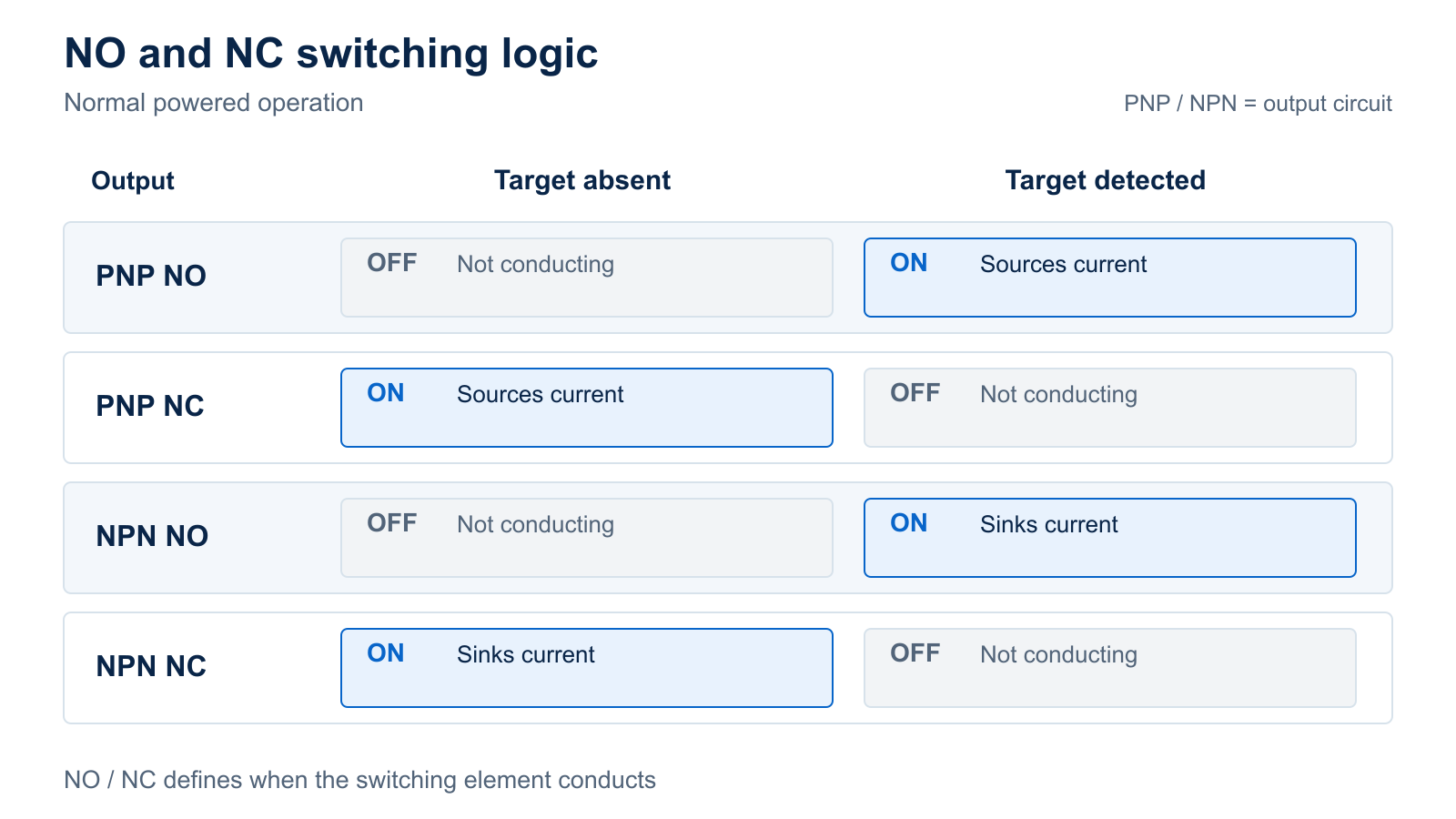
NPN and PNP describe the output circuit. Normally open and normally closed describe when its switching element conducts relative to the defined detection condition. For a conventional proximity switch in normal powered operation, NO conducts when the target is detected; NC conducts when the target is not detected.
| Specified output | Target absent | Target detected |
|---|---|---|
| PNP, NO | Output switching element OFF | Output sources current |
| PNP, NC | Output sources current | Output switching element OFF |
| NPN, NO | Output switching element OFF | Output sinks current |
| NPN, NC | Output sinks current | Output switching element OFF |
The table describes switching functions, not guaranteed voltage measurements at an unloaded terminal. An OFF transistor output is not necessarily a driven opposite-voltage output. The connected input, leakage and circuit design affect the measured state.
Changing a PLC condition from true to false can reverse how software interprets a valid input. It does not change a sensor's transistor circuit from NPN to PNP. Similarly, complementary NO/NC outputs mean opposing switching functions; the term does not by itself specify one NPN and one PNP output. Request the actual circuit and contact functions when more than one output is proposed.
Define Target-Present, Target-Absent and Startup Behavior
Write the required event in machine terms: for example, “part at inspection position” rather than simply “sensor ON.” Then connect that event to the electrical output state, the physical input state and the program's intended interpretation. This prevents a correct NO/NC order from being assigned the wrong meaning during commissioning.
Document startup separately. A sensor has an availability interval after power is applied, and the controller may also have startup sequencing. Ask which output behavior is documented during that interval and when the machine may begin using the signal. Do not assume the normal target-state table describes every moment of power-up.
Power loss, a disconnected conductor and a genuine target change must also be considered in the machine's control design where relevant. Choosing NC alone does not establish how the entire system distinguishes those events or qualifies a protective function. The OEM should state the required machine response and have the applicable control design reviewed separately.
Define Electrical Limits for the Complete Signal Chain
Supply Range, Load Current and ON/OFF Input Thresholds
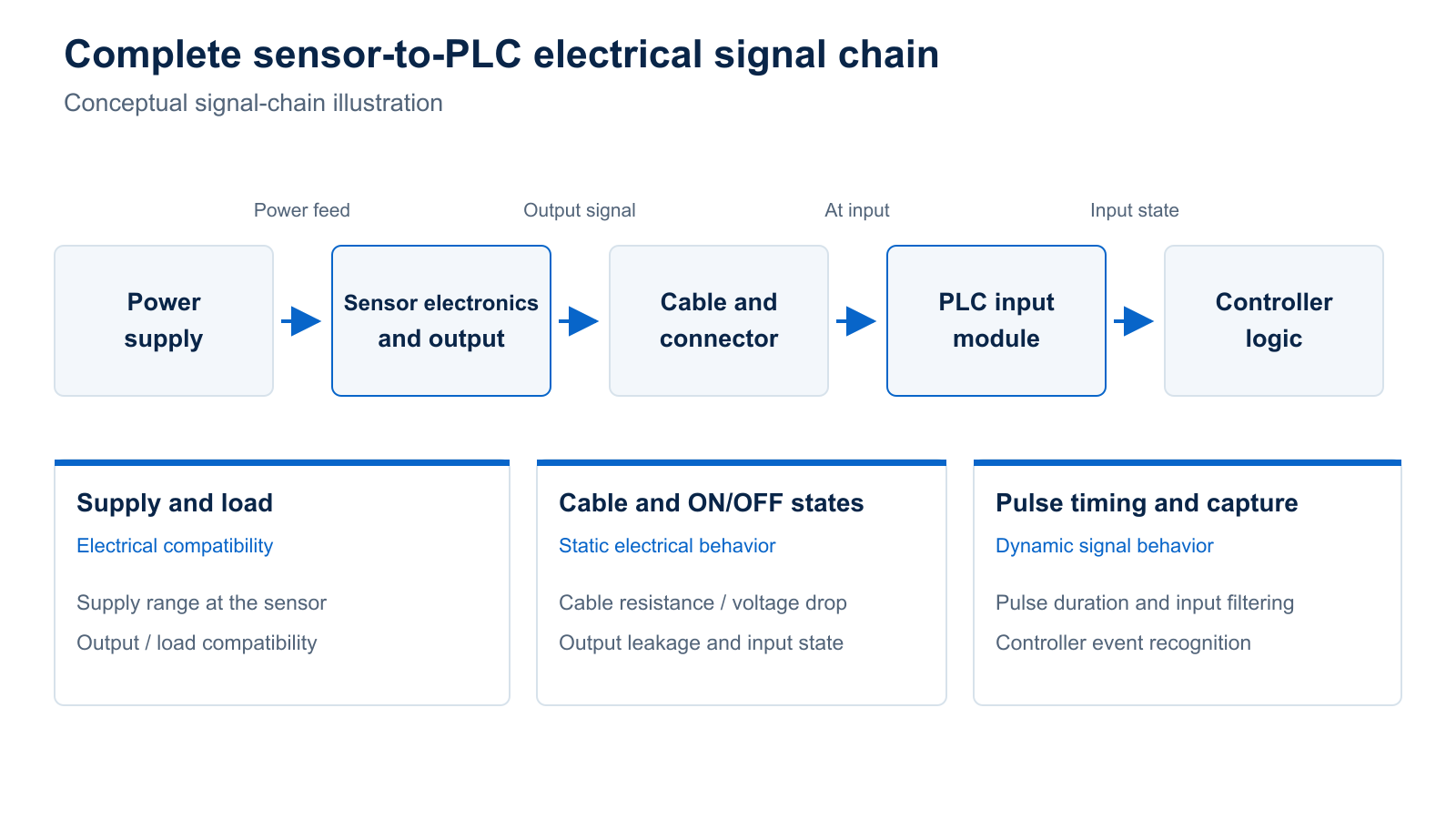
Specify the supply conditions at the sensor, including the lowest and highest conditions expected in the installation. A nominal power-supply label does not show what reaches the device through its complete cable and connections. The sensor must remain within its documented operating limits while the intended load is connected.
Separate the current used by the sensor itself from the current carried by its switching output. The output rating must accommodate the receiving load under the conditions defined for that rating. Where the selected architecture specifies a minimum load, that requirement belongs in the comparison too.
The receiver's ON and OFF requirements complete this check. Compare the proposed output behavior with the input's documented voltage and current criteria in both states, using the same reference and operating conditions. A proposal that confirms the sensor supply range but omits receiving-input compatibility has answered only part of the question.
Voltage Drop, Leakage Current and Cable Effects
A conducting transistor output is not an ideal connection with no voltage loss. Its specified voltage drop changes the voltage available across the receiving load. In the OFF state, the relevant leakage or residual current can matter if the receiver is sensitive enough to interpret that current as a signal.
Two-wire sensors need particular care because their operating arrangement places the sensor and load in the same current path. Their off-state current and residual voltage must be evaluated for that architecture. A two-wire proposal should not be treated as a three-wire NPN/PNP replacement solely because both are described as DC proximity switches.
Cable choice is part of the electrical comparison. Resistance contributes to voltage loss under load, while output loading can include cable capacitance. Obtain the permitted cable and load conditions for the proposed device instead of selecting a universal maximum cable length. The useful confirmation is that the agreed assembly works with the receiving circuit, not that a longer cable can physically be attached.
Pulse Timing and Controller Capture
A correct static input state does not prove that the controller can capture a short event. The sensor's operation and release timing describe how it responds to detection changes; switching frequency describes repetitive operation under specified test conditions. Neither figure alone establishes the machine's usable event rate.
Describe the shortest required target-present and target-absent intervals at the detection point. Compare the resulting output behavior with the input module's filtering and pulse requirements, then with the program or event-capture method. Both the active interval and the interval needed to recognize the next event can affect the result.
For intermittent faults at production speed, observing the output and receiving input during the same event is more useful than confirming that the indicator turns on during a slow hand test. Define the required timing evidence before accepting the custom interface.
Put the Cable, Connector and Pin Assignment in the Same Specification
Connector Format Does Not Define Output Type or Pinout
A matching connector establishes a mechanical connection only after its relevant geometry has been checked. It does not, by itself, identify the output circuit or the function assigned to each contact. “M12 connector” is therefore incomplete as an electrical requirement.
Provide a connection drawing that identifies the connector format, coding, contact count, orientation and the view from which contact positions are shown. Each contact must have a defined function, with the mating cordset or connection included in the review. Do not infer that an unused contact on one variant becomes a second switching output on another.
For a custom sensor, the mechanical drawing, electrical diagram and quotation should refer to the same configuration. If the connector description agrees but the contact assignment differs, resolve that difference before the sample is connected.
Cable Requirements, Drawings and Replacement Identification
Describe the cable as an installed component: required length and its reference points, cable exit, routing space, bending or movement, and relevant exposure. A jacket that fits the space has not thereby been shown suitable for the actual fluids, cleaning or movement in the machine.
The supplier's response should identify the proposed cable construction and applicable limits. Where the requested assembly differs from the documented standard version, ask which existing evidence remains applicable and what the revised assembly needs to demonstrate. This keeps a connection change from becoming an undocumented assumption about environmental performance.
Link the agreed connection drawing to the complete order code and revision. An OEM part number can simplify purchasing, but maintenance also needs a reliable way to distinguish electrically different variants that look alike. A replacement record should lead back to the approved configuration, not just a photograph of its connector.
Separate Interface Customization From Detection Performance
Preserve the Target, Working Gap and Mounting Requirements
Changing the output interface solves an electrical integration problem. It does not establish that the proposed sensing design can detect the OEM's target at the installed gap. Keep the target material, relevant dimensions, approach path, mounting and operating variation in the specification even when the immediate request concerns PNP or NPN.
For an inductive sensor, the reference target used to specify sensing performance is not automatically equivalent to the production part. A smaller feature, different metal or different path may change the detection condition. The supplier must review the actual detection task as well as the requested output.
State which properties must remain unchanged from an existing qualified installation. If a proposed custom version changes both the interface and the sensing arrangement, evaluate both changes. Otherwise, a successful electrical substitution can conceal an unresolved detection problem.
Standard Variant, Configurable Output or New Engineering?
Start with an available documented variant when it already meets the requirement. A PNP version within a product family may address the interface without requiring a new sensor design. Its exact order code and specifications still need confirmation; a family-level option does not identify the unit being purchased.
Some products instead provide configurable output behavior. For example, the ifm IM5172 data sheet, revision IM5172-02 specifies parameterizable PNP/NPN operation and selectable NO/NC behavior. That is evidence for that device, not a capability to assume for every proximity sensor or an XSZ custom model.
A fixed variant, a configured device and a new engineering design have different approval needs. A configured device needs its required settings recorded; a new design needs the feasibility, documentation and sample evidence appropriate to its changes. Ask the supplier to identify which route its proposal follows before treating “custom output” as a settled specification.
Worked Decision: Accept or Reject an OEM Interface Proposal
The following example is hypothetical. It shows how to assess a reply and does not describe an XSZ product, customer installation or completed test.
Why a Matching Connector Can Still Leave the Proposal Incompatible
Assume an OEM has documented an input circuit that requires a sourcing PNP sensor. The machine must recognize the detected part as the active input state. Its bracket and mating connector are already defined.
A supplier offers an NPN/NO sensor with the requested connector and housing. The physical description appears suitable, and the normal switching function agrees with the target event. Nevertheless, its output does not provide the sourcing path required by the specified input. Classify the proposal as incompatible with the existing interface, rather than planning to fix it by reversing a software condition.
A second reply offers PNP/NO with the same connection format. This resolves the first mismatch but does not complete the assessment. The output rating, receiving-input requirements and exact contact assignment still have to agree. The second proposal is a candidate for further review, not an approved replacement simply because its label is more promising.
Resolve Missing Data Before Approving a Sample
Suppose the second reply omits its maximum output voltage drop and OFF-state current information. Those omissions prevent a complete comparison with the receiver's ON/OFF requirements. Record the relevant items as pending and ask for the exact proposed device data or an agreed method to resolve the missing evidence.
Treat the outcomes differently: a documented mismatch calls for a revised interface proposal; missing data calls for clarification; a supported documentary match can proceed to representative sample validation. If the OEM elects to change the input hardware or wiring, that is a separate machine modification requiring its own review.
This approach makes the next supplier request specific. It also prevents a passed mechanical check from being used as evidence for an electrical question it never tested.
Validate and Freeze the Agreed OEM Configuration
Test Both Switching States With the Intended Receiving Input
Use a sample that represents the proposed configuration, including its output version, connection and applicable settings. Identify the sample and its documents before the evaluation. A test of a different cable assembly or output variant cannot settle every question about the ordered version.
A useful interface evaluation has three linked observations:
- Confirm the supply at the sensor under the intended connected load and relevant machine conditions.
- Observe the output in target-present and target-absent conditions, including the required event timing.
- Confirm that the intended receiving input and machine logic recognize the corresponding states and events.
Record the setup and acceptance limits before calling the result a pass. A failed receiving-input observation can arise from the sensor output, the connection or the receiver configuration; locate the disagreement before attributing it to the sensing element.
Carry out installation and testing under the machine's applicable safe procedures. This interface check does not authorize live rewiring, deliberate fault injection or substitution for a separately required protective system assessment.

Approve the Drawing, Order Code and Change-Control Record
Release an identifiable configuration with evidence, rather than an informal description such as “the PNP sample.” Retain the agreed mechanical and connection drawings, output and switching function, relevant settings, acceptance record and unresolved restrictions. Make the purchase order refer to that baseline.
When the supplier proposes a change, identify the affected requirement and decide which evidence needs review or repetition. A revised contact assignment raises a different question from a changed label layout. Neither should be hidden behind an unchanged sales description.
A sample approval supports the evaluated configuration and conditions. Maintaining that definition in production requires the agreed identification, inspection and change process; a sample pass does not establish every future unit or service condition.
What Should You Send With a Custom Sensor RFQ?
Send one coherent requirement packet with a named technical owner. The supplier should be able to identify the receiving circuit, propose a specific configuration and mark each important item as confirmed, conditional or unresolved.
| Requirement group | Buyer supplies | Requested supplier response |
|---|---|---|
| Receiving interface | Input-module identification, relevant circuit and common connection | Compatibility statement for the proposed output and actual input |
| Switching behavior | Detection event, target-present/absent states and startup requirements | Exact NPN/PNP and NO/NC function, output count and documented availability behavior |
| Electrical and timing limits | Supply conditions, receiving load and thresholds, required event intervals | Applicable ratings, ON/OFF limitations, timing and any conditions still needing evaluation |
| Cable and connection | Assembly length, routing/exposure, mating connection and required contact functions | Connection drawing, proposed assembly, applicable limits and revision |
| Detection and installation | Target information, working-gap range, motion, mounting and operating conditions | Suitable candidate specification and the limits or changes requiring review |
| Approval and procurement | Sample needs, acceptance criteria, expected quantity and requested schedule | Identified sample/configuration, open items and configuration-specific commercial terms |
For preparation, xsz sensor's output-type information provides a related technical entry point. Use the customized-models enquiry context to submit the machine requirements and supporting documents for a feasibility discussion. Neither link confirms a particular electrical limit, development schedule or available combination.
Ask for a response that connects each proposed option to the requirement it satisfies. The useful purchasing result is an agreed technical version and a defined approval path, with remaining questions visible before the production order.
Technical References
- Schneider Electric — PNP and NPN in Three-Wire Sensor Connections: circuit selection, PLC input matching and the distinction from NO/NC logic.
- OMRON — FAQ00379: NPN and PNP Transistor Outputs: load placement relative to supply and output.
- Balluff — Inductive Sensors: Basics and Installation: electrical terms, output circuits and connection considerations, printed pages 2–6.
- OMRON — Proximity Sensors: Further Information: two-wire leakage and residual-voltage behavior.
- OMRON — Proximity Sensors: Explanation of Terms: reference targets, response characteristics and switching functions.
- Pepperl+Fuchs — Output Logic of Switching Sensors: NO, NC and complementary switching functions.
- ifm — IM5172 Inductive Sensor with IO-Link, IM5172-02, 13 April 2023: a device-specific example of configurable output behavior.