

Sensor Terminology
Current
Meaning, Types and Importance for Sensors
Electric current is the rate at which electric charge flows. Learn what amperes mean, how current moves through a circuit, and how to read the different current ratings on an industrial sensor.
Understand currentWhat Is Electric Current?
Electric current is the rate of flow of electric charge through a point in a circuit. Its SI unit is the ampere (A): one ampere equals one coulomb of charge passing a point each second. A milliampere (mA) is one-thousandth of an ampere, so 1 A = 1,000 mA.
A source establishes a voltage difference; current flows when there is a conductive, complete path through the load and back to the source. The amount of current depends on the circuit—not on voltage alone.
Diagrams normally use conventional current, from positive to negative. In a metal wire, electrons drift the other way. Both describe the same circuit using different direction conventions.
Common Current Types
Direct current (DC)
Current flows in one direction. Its magnitude can be steady or can vary without reversing direction.
Alternating current (AC)
Current reverses direction periodically. Mains-powered equipment is a common example; check the device rating before connection.
Output or load current
Current in the external circuit controlled by a sensor output. It must stay within that output's specified rating.
AC and DC describe how current behaves over time. “Load current” describes where current flows in an application; it is not a third waveform type.
Which “Current” Does a Sensor Datasheet Mean?
Sensor specifications use similar units for different circuits. Read the label and test conditions before comparing values.
| Term | What it describes | What to check |
|---|---|---|
| Current consumption | Current drawn by the sensor electronics from its supply, often specified with no output load. | Budget the power supply for the sensor and all connected devices. |
| Output load current | Current flowing through the external load when a switching output is ON. A PNP output sources current; an NPN output sinks it. | Confirm load/PLC input demand does not exceed the exact output rating. |
| Maximum switching current | The stated upper current limit for a switching output under specified conditions. | Check the model, temperature, residual voltage and load type. |
| 4–20 mA signal current | A varying analog loop current that represents a measurement across a configured span. | Check loop power, input type and allowable loop resistance; do not treat it as a switching-output rating. |
| OFF-state leakage current | Small current that may still pass through certain output or two-wire designs while nominally OFF. | Check whether the receiving input or load could falsely remain active. |
Model-specific example, not an XSZ rating: one OMRON E2E small-diameter series lists 10 mA maximum sensor consumption while its permitted output load current varies by model from 50 to 200 mA. Those numbers serve different purposes.
Why Current Matters in Sensor Circuits
Power budget
The supply must support the combined demand of sensors, input modules and other devices, including operating conditions.
Output compatibility
A sensor output must match the connected input or load in topology, voltage and permissible current.
Analog measurement
A 4–20 mA loop communicates a continuous process value: 4 mA usually represents the configured lower range and 20 mA the upper range.
Fault diagnosis
An unexpected reading can point to a wiring, supply, load or device issue—but the interpretation depends on the exact circuit.
How Are Current and Voltage Related?
Voltage is the electric potential difference between two points; current is the rate of charge flow. For an ideal resistive load, Ohm's law relates them: increasing voltage across the same resistance increases current. Real sensor circuits also include electronics, output stages and input thresholds, so their datasheet ratings take precedence over a simple calculation.
For a purely resistive example, 12 V across 1 kΩ gives 0.012 A, or 12 mA. This is an illustration of Ohm's law, not a sensor specification or a 4–20 mA loop design rule.
Where Current Appears in Industrial Automation

Packaging line
DC sensors draw supply current while their switching outputs signal object detection to a controller.

Conveyor detection
Output load current and PLC input requirements must match the selected sensor interface.
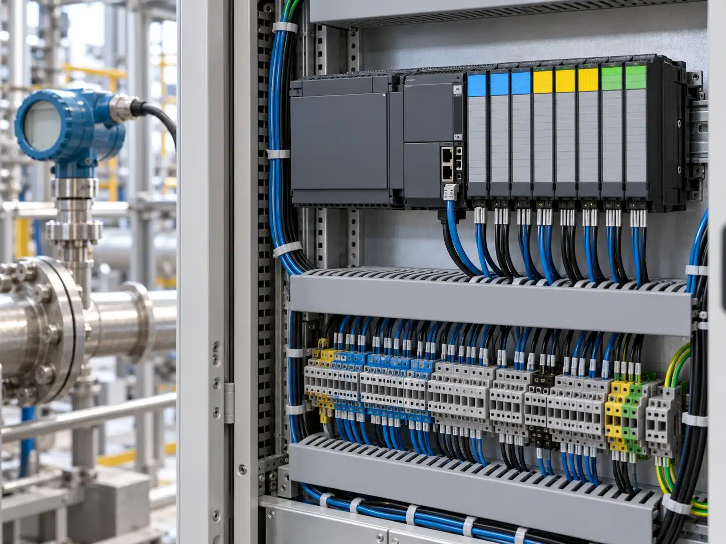
PLC and process measurement
Analog current loops can carry continuously changing values such as level, pressure or flow to a compatible input.
Current vs. Voltage
| Question | Current | Voltage |
|---|---|---|
| What is it? | Rate of electric-charge flow through a point | Electric potential difference between two points |
| Unit | Ampere (A), often milliampere (mA) for sensor circuits | Volt (V) |
| What does a rating tell you? | How much current a device draws, carries or can switch—depending on the label | The supply or signal voltage a device expects or produces |
| Typical check | Supply capacity, output load and input-current compatibility | Supply range, output level and input-voltage compatibility |
How Is Current Measured?
Current is measured in amperes with an instrument and range suitable for the circuit. A conventional ammeter or multimeter current input is inserted in series; an appropriate current clamp measures the magnetic field around one conductor. A voltage measurement is different: it is taken across two points. Follow the equipment manufacturer's instructions and site electrical-safety procedures before testing any live industrial circuit.
Frequently Asked Questions
What is the unit of electric current?
The SI unit is the ampere (A). In sensor datasheets, milliampere (mA) is common; 1,000 mA equals 1 A.
How much current does a typical sensor use?
There is no universal value. “Current consumption” depends on the exact model, supply voltage and operating conditions. Read that model's datasheet; do not confuse it with its output load-current rating.
What is the difference between AC and DC current?
DC flows in one direction, even if its magnitude varies. AC reverses direction periodically. A sensor's power-supply and output labels indicate which type it supports.
Can too much current damage a sensor?
Exceeding an output or supply rating can cause malfunction or damage. Some models have protection circuits, but protection type and limits vary; verify the exact specification.
Is 4–20 mA the same as sensor power consumption?
No. A 4–20 mA output is an analog measurement signal in a loop. Current consumption describes what the sensor electronics draw from their supply. In a loop-powered transmitter these interact, but the terms are not interchangeable.
Does a 24 V sensor always draw the same current?
No. “24 V” usually names a supply voltage, not a current draw. Actual consumption depends on the device and conditions, and current through the output load is a separate specification.