
Capacitive vs. Inductive Proximity Sensors: Which Detects Your Target?
Start with an inductive sensor for metal targets. Consider a capacitive sensor for suitable plastic, glass, liquid, or powder targets, as well as metals. The deciding question is whether the selected model can reliably distinguish the required target-present and target-absent states in your actual installation.

Quick Comparison: Capacitive vs. Inductive Sensors
Use this comparison to choose a sensing principle to investigate. It does not establish a model's usable distance or suitability for a particular material.
| Selection question | Inductive proximity sensor | Capacitive proximity sensor |
|---|---|---|
| What produces the response? | Electromagnetic interaction with a conductive metal target. | A change in capacitance as material affects the sensing field. |
| Which targets are candidates? | Ferrous and nonferrous metals, with model-dependent response. | Metals and suitable nonmetals, including some plastics, glass, liquids, and powders. |
| Can the catalog distance be used unchanged? | Check the specified reference target against the actual metal and geometry. | Check the reference conditions against the actual material, size, and position. |
| Can it detect contents through a container? | Not a general starting point for nonmetallic contents behind a nonmetallic wall. | Possible with a suitable model and wall/material combination; distinguish contents from the wall itself. |
| What nearby conditions need attention? | Surrounding metal, mounting geometry, and adjacent sensors. | Surrounding materials, mounting geometry, adjacent sensors, and relevant moisture or deposits. |
| Does the principle determine the electrical connection? | No; verify the ordered output and receiver. | No; verify the ordered output and receiver. |
The wider material response of capacitive sensing can solve a detection problem that an inductive sensor cannot. It also creates a selection question: which other materials in the sensing area could produce a response? That is particularly important when the target sits inside packaging or close to a machine structure.
How the Detection Principles Change the Target Choice
Both technologies convert a nearby physical change into an electrical signal. Their difference lies in the interaction that creates that change, rather than in the shape of the housing.
Inductive Sensing: Eddy Currents in a Metal Target
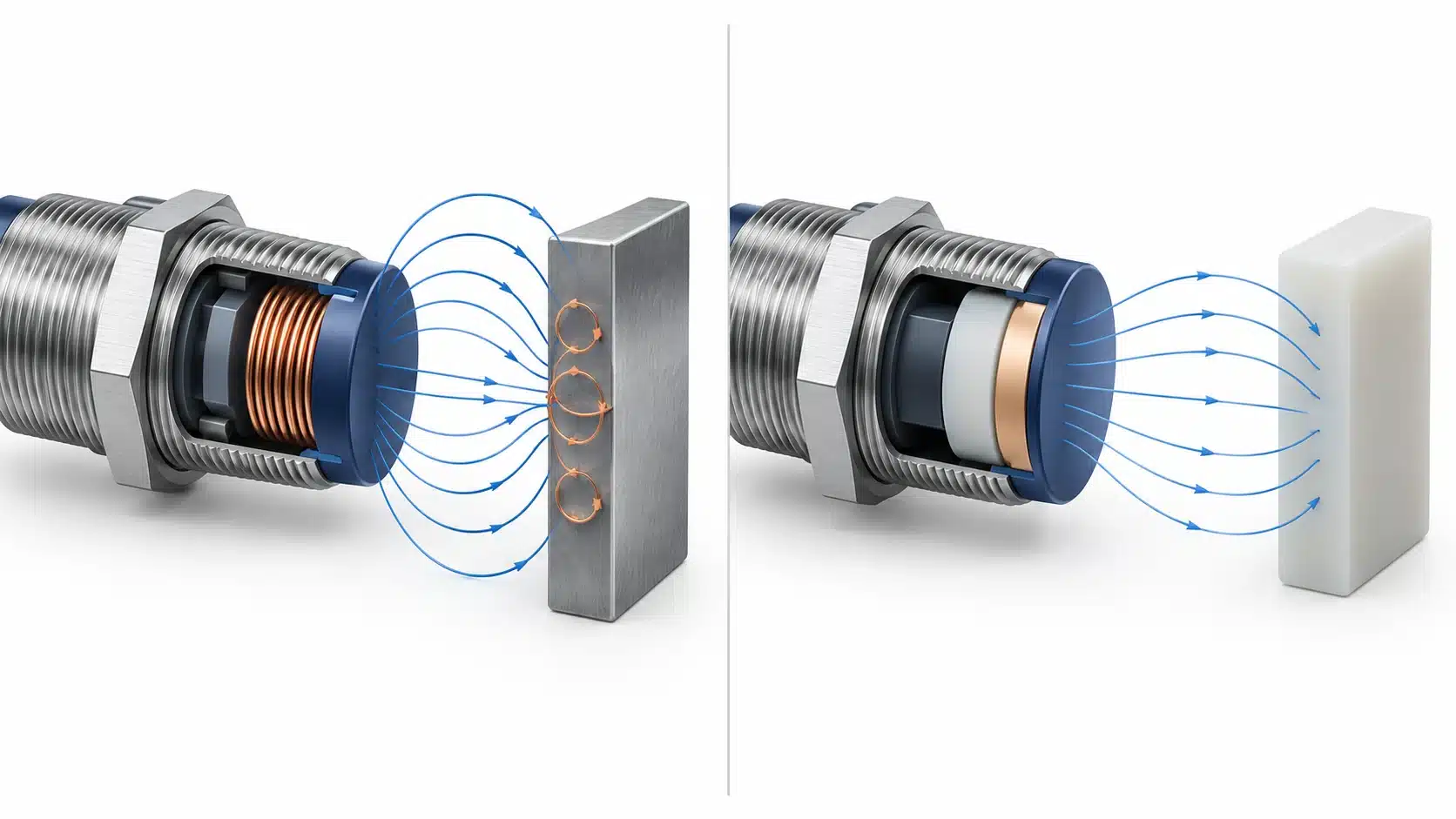
A common inductive proximity sensor generates an alternating magnetic field at its sensing face. A conductive metal entering that field develops circulating currents called eddy currents. Their interaction changes the electrical behavior of the sensing coil, which the sensor evaluates to switch its output.
This explains why an inductive sensor is a useful starting point for a metal component: the component participates in the detection mechanism. It does not normally need an attached magnet. Nonferrous metals can also be detected, although the usable distance need not match that for steel.
For selection, identify the metal feature that should cause the signal. A sensor intended to confirm a small metal insert must respond to the insert rather than a nearby bracket. Calling the assembly a “metal part” is insufficient if most of the material within reach belongs to the fixture.
Capacitive Sensing: A Change in the Electric Field
A capacitive sensor evaluates a change in capacitance around its sensing face. Conductive objects and suitable nonconductive materials can change that response. For nonconductive targets, dielectric properties describe how the material responds to the electric field; size and position also affect the resulting change.
This gives capacitive sensing a broader target range. It does not make it a material identifier. A switching response indicates that the configured detection condition has been reached, not that the sensor has recognized “plastic,” “water,” or another material by name.
Choose it when the wanted material produces a distinguishable change under the intended conditions. If several surrounding objects also influence the field, the installation must separate their influence from the change caused by the target.
Match the Sensor to the Target You Need to Detect
Define the event before comparing models: a metal feature reaches position, a package arrives, or contents reach a level. These tasks can involve the same assembly while requiring different sensing behavior.
Metal Parts, Alloy Changes, and Small Features
Inductive sensing can suit metal presence and position checks. However, a successful check with one metal sample does not qualify another alloy or target geometry. Metal-dependent response is a reason to review the selected model's data when a production part changes from steel to aluminum, for example.
Special inductive designs are available with reduced differences between specified metals. Such behavior must be documented for the candidate model; it cannot be inferred from the word “inductive” or from an identical housing.
Describe a small target by the feature presented to the sensing face, not just the overall part dimensions. For a proposed pin-detection task, evaluate the exposed pin at its permitted positions rather than using a large metal plate as the acceptance sample. The practical question is whether that feature creates a repeatable switching change while the surrounding fixture does not.
Plastic, Glass, Liquids, and Powders
Capacitive sensing is worth evaluating when a nonmetallic target must be detected without contact. A plastic component, a glass object, a liquid, and a powder may all be candidates, but they do not present equivalent electrical or geometric conditions.
A published range established with a reference target does not prove the same range for a small plastic feature. Likewise, “powder” does not specify one consistent target: the material and the way it occupies the sensing region must be defined. A useful evaluation includes the actual product and the expected variation in how it reaches the detection point.
For a proposed filling application, define what the output should indicate. Detecting that material is near the sensor is different from measuring how much material is in the vessel. A proximity switch should not be treated as a continuous quantity measurement merely because its output changes during filling.
Container Presence Is Different From Contents Detection
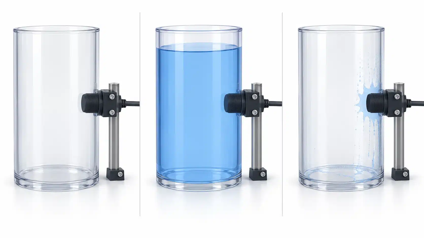
If the task is bottle presence, a response to the bottle wall may be useful. If the task is liquid presence inside that bottle, a response to the empty wall is a problem unless the selected configuration can still distinguish the required contents states.
Through-wall detection is possible with suitable capacitive designs and nonmetallic containers. It depends on the particular sensor, wall, medium, and installation. A model documented for one container arrangement does not establish a general capability through any plastic, glass, or metal vessel.
For a contents check, compare the same container empty, filled to the required condition, and emptied with realistic remaining deposits. This separates three questions: can the sensor respond to the contents, can it avoid treating the empty container as contents, and can it reset after the process? The test must resolve all three before the arrangement is accepted.
Compare Usable Distance and Mounting Conditions
A workable sensor needs both a suitable interaction and a feasible position on the machine. Compare the complete detection arrangement rather than selecting the largest distance printed in a catalog.
Nominal Range vs. the Actual Target and Path
Published sensing-distance definitions refer to specified targets and test conditions. The actual target's material, dimensions, approach, and surroundings may differ. Use those differences to decide which specification or application data is relevant; do not apply a generic distance percentage to every model.
For a moving target, identify its farthest permitted position from the sensor and the smallest feature that must be detected there. Then identify the nearest unwanted object when the target is absent. The desired installation must support both a reliable detection state and a reliable clear state.
Operation and reset positions also differ by the sensor's hysteresis. A target that just causes a switch during approach may not release the output at the same position during withdrawal. Include both directions where they occur in the machine, particularly when a part pauses or moves near the switching boundary.
Nearby Metal, Brackets, and Adjacent Sensors
The support structure is part of the sensing environment. Nearby metal can affect an inductive sensor, while surrounding materials can influence a capacitive sensor. Adjacent sensors can also interact. A bench check away from these influences is useful for initial screening, but it does not qualify the final mounting position.
Review the candidate's flush or nonflush mounting requirements, surrounding clearances, and permitted spacing from other sensors. These are model requirements, not universal dimensions attached to a technology name. Replacing a sensor with a longer-range version may require a fresh mounting review even when the new unit fits the existing hole.
Make the final check with the intended bracket and neighboring equipment in place. If bringing the fixture into position changes the output without the target, resolve that influence before adjusting the sensor to detect the part.
Check Moisture, Deposits, and Process Variation
Separate environmental durability from detection behavior. A device can be suitable for a stated exposure while material near its sensing face still changes what it detects. Conversely, a clean switching test does not establish that the housing or connection is suitable for cleaning chemicals or washdown.
With capacitive sensing, increasing sensitivity can make a weak target easier to detect while increasing the influence of unwanted moisture or dirt. Adjustment should therefore establish separation between the required states, rather than simply produce an output with the target present.
Residue handling is also design-specific. For example, the SICK CQF16 manual describes calibration with expected deposits, foam residue, or moisture present. This is evidence for a documented feature of that model, not a procedure or compensation guarantee for every capacitive sensor or an XSZ model.
For the proposed installation, decide which process changes can alter the target or surroundings: a damp container, remaining material after emptying, or nearby metal debris. Challenge the relevant changes within the device's documented limits. If the target-absent condition begins to resemble the target-present condition, a sensitivity change alone may not provide a workable solution. Reconsider the mounting, target presentation, or sensing method.
Match the Switching Signal to the Controller
The sensing principle does not specify the output circuit. Verify the exact ordered variant, its supply requirements, and the receiving input before treating two sensors as interchangeable.
NPN and PNP describe transistor-output arrangements; normally open (NO) and normally closed (NC) describe switching behavior. They answer different questions. The correct selection must provide the electrical signal the receiver accepts and the logic the machine expects for target presence and absence.
For a programmable logic controller (PLC), review the sensor output limits alongside the input specification. Where applicable, include off-state leakage and on-state residual voltage, rather than checking supply voltage alone. Do not infer wiring from housing size, technology, or a familiar cable color.
Dynamic operation needs a separate check. Response time describes a switching delay; switching frequency describes repeated operation under defined conditions. Neither label alone establishes that the controller will capture a short target event. Verify the sensor's operation and release behavior together with the receiving input's filtering and capture requirements, using the actual movement and gaps. A sensor indicator changing state is not proof that the machine registered the event.
Validate the Choice With Production Samples
Use a controlled commissioning procedure appropriate to the machine. Make wiring or mounting changes with the relevant equipment isolated, and perform operating tests without entering hazardous motion. These checks concern ordinary process detection; they do not qualify a sensor as a personnel-protection device.
Challenge Both Required States
The following is a recommended validation sequence, not a record of completed product testing:
- Write down the required states. Define exactly what must be present to trigger detection and what must count as absent. For contents sensing, describe the container and residual material as well as the contents.
- Select difficult representative samples. Include relevant material variants, the smallest detection feature, and permitted position changes. For a bulk material or liquid, include the process variations that could change the response.
- Use the final mounting arrangement. Fit the intended bracket and include neighboring structures or sensors. Confirm both target-present and target-absent behavior before relying on a nominal range.
- Check approach, withdrawal, and dwell. Establish where the output operates and resets. Include pauses and reverse movement if they are part of the process.
- Repeat under relevant operating conditions. Check the actual movement and gaps, then challenge expected moisture or deposits within the documented application limits. Observe the receiving input as well as the sensor.
- Retain the acceptance record. Record the model and settings, target samples, mounting, conditions, observed output/input behavior, and agreed pass criteria. Investigate inconsistent states before confirming the choice.
A useful result is a documented arrangement that separates the required states across the tested conditions. One successful activation with an easy sample is only an initial observation.
Information to Provide for Model Selection
Send the supplier enough information to evaluate the detection point:
- Target material, relevant alloy or product variation, dimensions, and the feature to be detected.
- Required target-present and target-absent states, including container wall and contents where relevant.
- Available mounting space, actual gap and target path, surrounding structures, and adjacent sensors.
- Motion, dwell, and gaps between targets, plus the receiving input and its capture requirements.
- Supply, output circuit, switching logic, connector requirements, and relevant environmental exposure.
- Representative samples and the conditions under which the selection must be accepted.
For an XSZ inquiry, use the inductive proximity sensor category or capacitive proximity sensor category as the appropriate starting point. Discuss the detection task and confirm the candidate model's applicable documentation before ordering; the category name alone does not establish that a particular target will be detected.
Technical Sources
- OMRON — Overview of Proximity Sensors. Sensing principles, target categories, and surrounding-object effects.
- OMRON — Proximity Sensors: Explanation of Terms. Reference targets, sensing distance, hysteresis, timing, and output terminology.
- Balluff — Inductive proximity sensor targets: Material does matter, June 18, 2024. Metal-dependent response and specialized inductive designs.
- Balluff — What is a capacitive sensor?, March 4, 2024. Target properties, reference conditions, and sensitivity trade-offs.
- SICK — CQF16 Operating Instructions, 8022710.1EAN/2022-05-31, English pages 18 and 22. Model-specific through-wall application and calibration conditions; not XSZ product specifications.