
Can Background Suppression Sensors Detect Dark or Reflective Targets?
Yes, a background suppression sensor can detect some dark or reflective targets, but the result depends on the target's optical return, its distance and angle, the nearest background, and the exact sensor model.

Background suppression helps reject a farther surface; it cannot recover light that a dark part fails to return or make a shiny part reflect consistently. Select a candidate by checking its documented limits, then test actual parts in both target-present and target-absent conditions across the machine's full operating range.
Quick Check: What Must Be True?
Before comparing headline sensing ranges, define the two states the machine must distinguish: a required part in the detection position and an empty detection point with its real background visible. The following checks show whether a candidate deserves a production-sample trial. They are questions to verify, not performance specifications for every background suppression sensor.
| Check | What must be confirmed | Practical test or document |
|---|---|---|
| Darkest required target | The receiver gets a usable return at the farthest permitted target position. | Check the candidate model's target-color or material guidance; test the actual darkest sample and finish. |
| Target–background window | Every required target can be detected while the nearest permitted background remains rejected. | Measure both distance ranges through full travel and compare them with the model's setting range and stated conditions. |
| Reflective surfaces | Changes in angle, curvature or orientation do not cause missed or false switching. | Present production samples at their permitted extremes, including their edges. |
| Smallest feature and light spot | The required feature sufficiently covers the spot at the real detection position. | Check the model's spot information and test the smallest required feature along its complete path. |
| Electrical result | The sensor and receiving input distinguish both states at operating speed. | Observe the electrical output and the controller's captured state in the installed circuit. |
The important outcome is a usable detection window, not a single successful trigger. A sensor that detects one carefully positioned black sample can still miss a darker, farther or differently oriented part; a sensor that ignores one background position can still switch when the background moves closer.
Why Dark Targets May Be Missed
Low Return and Color-Related Sensing Distance
A background suppression sensor emits light and evaluates light returned from the target. A dark or low-reflectance surface may return less usable light than a light-colored reference at the same location. If the returned signal falls below what the receiver and selected operating mode need, changing the cutoff alone cannot make the part visible. Visible color is an imperfect shortcut: the relevant return depends on the material and finish at the sensor's emitter wavelength, as well as position and angle. Test the actual material rather than assuming that every black part behaves alike.
This is why a sensing distance quoted for one reference target cannot be transferred automatically to a dark production part. The dark target may need to be closer to the sensor for a stable response, depending on the optical design. Check the candidate model's conditions and target-color behavior, then confirm the response at the farthest position that the mechanism permits. Do not use a bright sample to accept a setup intended to detect a darker one.
Dark Targets Against Bright Backgrounds
A bright background can return more light than a dark target even though it is farther away. Background suppression is intended to discriminate by the applicable distance setting, rather than treating the strongest return as the required target. That distinction is useful only if the sensor can still see the dark target and if the background stays outside the model's usable detection region.
Consider the worst geometric combination, not just the nominal drawing: the dark part at its farthest allowed position and the bright background at its nearest. Allow for bracket adjustment, part travel and normal assembly variation when measuring those positions. Then check whether the candidate model provides a setting that detects the part in that combination without accepting the empty-path background. If the two conditions cannot be separated under the model's documented limits, merely turning a sensitivity control is not a sound selection method. Change the mounting geometry or evaluate another sensing arrangement.
Why Reflective Targets Can Give Unstable Results
Specular Return, Angle, and Curved Surfaces
A shiny target is not automatically easy to detect. A matte surface scatters light in many directions; a smooth reflective area may redirect much of it away from the receiver. At another angle, a strong reflection may reach the receiver. As a curved or angled part moves, the return can change even when the part remains within the intended distance. The resulting symptom can be a missed part, switching only at an edge, or an output that changes more than once during a pass.
Check the face, edges and curved portions that actually enter the spot. Rotate or translate a representative sample through the orientations allowed by the machine and observe the output, not only the sensor indicator. A mounting-angle adjustment may improve one optical path, but it can also change the apparent target distance and the background view. Use the selected model's mounting guidance and repeat the full target/background check after any adjustment. There is no universal tilt angle that makes every reflective target reliable.
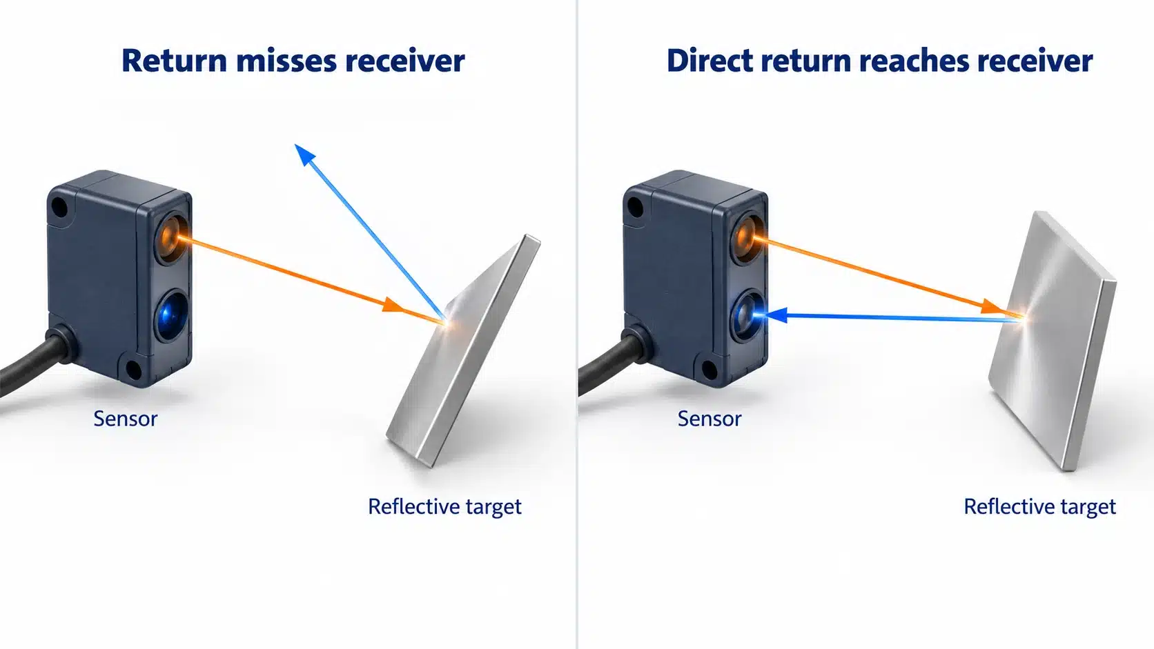
Reflective Backgrounds and Changing Geometry
The empty path matters as much as the shiny part. A metal guard, polished machine surface or moving reflector in the background can create a return that changes with angle and position. Background suppression may reject a sufficiently distant surface under the selected model's conditions; it is not a guarantee of immunity to every reflective background. A background that moves nearer or sends an unfavorable return into the receiver can defeat a setup that worked during a stationary trial.
Identify what the sensor sees when the target is absent. Test the nearest and most reflective permitted background positions, including other machine parts that enter the field during a cycle. If the sensor switches with no target, separate a background/geometry problem from a target-return problem before changing the setting. A single adjustment should be judged against both states; improving target detection while causing empty-path triggers is not an improvement.
Confirm the Usable Detection Window
Farthest Target and Nearest Background
Record distances from the mounting reference used in the candidate model's documentation. For the target-present state, include the farthest required target position and the least favorable material or finish. For the target-absent state, include the nearest background surface and any permitted movement. Compare those measured ranges with the model's stated operating conditions and any color- or material-dependent shift. Also check its near limit if the part can approach the sensor closely; a maximum-range figure alone does not define the whole usable region.
The selection question is whether one documented configuration can keep all required targets detected and all permitted empty-path backgrounds rejected. There is no sound universal millimeter gap to insert between the two; required separation depends on the candidate's optics, the surfaces and the installation. If the required states overlap under the documented and tested conditions, request a different model or revise the sensing position instead of treating a nominal cutoff value as proof of margin.
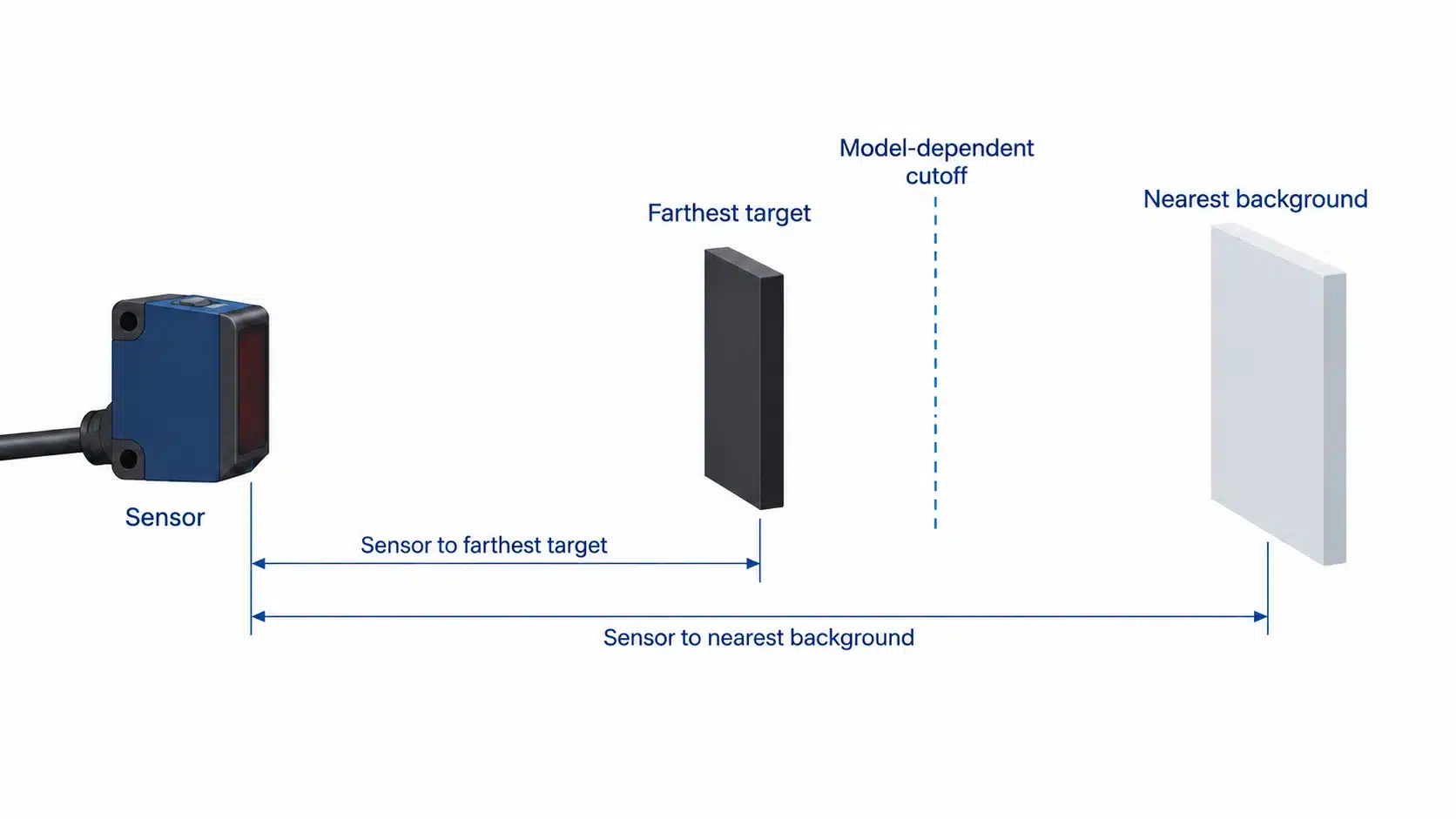
Spot Size, Edges, and Part Travel
Distance separation does not solve every small-part problem. When a feature covers only part of the light spot, the sensor may receive a mixture of target and background returns. A dark edge against a bright background is especially worth checking: the target's weak contribution can change as the edge enters or leaves the spot. A minimum object size in a data sheet applies only under its stated conditions and should not be read as a promise for every color, distance or travel path.
Sketch the smallest required feature and its entire permitted path across the beam. Check whether the spot is sufficiently covered at the positions where the controller must recognize the part. Include lateral motion, tilt, vibration and the transition at both leading and trailing edges. If the usable state exists only for a very short interval, the electrical and controller timing must also be checked; a stable bench indication at rest does not establish reliable production detection.
Validate With Production Samples
Test Target-Present and Target-Absent Conditions
Build a small test set from real production extremes: the darkest finish, the glossiest or most curved surface, the smallest required feature and relevant manufacturing variation. Use the final mounting arrangement where possible. Record the target distance, angle and position for each trial, along with the nearest and most reflective background. The purpose is to establish which combinations pass, not to produce an attractive one-off demonstration.
First confirm the required target state at the farthest and least favorable permitted positions. Then remove the target and confirm the opposite state with the real background visible throughout its permitted movement. Repeat after changing only one controlled variable at a time, such as orientation or mounting position. Test the complete machine cycle and the environmental conditions relevant to the application, within the chosen model's ratings. If a failure appears, note whether it is a missing target return or a false background return; those call for different corrections.
Do not describe these checks as completed XSZ laboratory results. They are a validation plan for the buyer and machine builder. The acceptance criteria should come from the actual process: which part features must be detected, which empty-path appearances must be ignored and what repeatability the control system requires.
Confirm the Controller Input at Operating Speed
A switching indicator shows what the sensor reports locally; it does not prove that the receiving input captured the event. Verify the supply and output circuit against the exact model documentation, then observe the sensor's electrical output and the controller input during the same pass. Confirm the output logic and input compatibility before interpreting a missed count as an optical failure.
Run at the intended production speed and at relevant slower and faster permitted conditions. If the sensor output changes correctly but the controller misses it, check the documented response behavior, output interval, input filtering and capture logic. If the sensor output is itself unstable, return to the optical path, target/background window and mounting. Keep those two failure locations separate; changing the cutoff will not fix an incompatible or insufficiently captured electrical signal.
When Another Optical Arrangement May Work Better
If the required dark target does not return enough light, or if target and background cannot be separated over the permitted geometry, evaluate whether the machine can detect beam interruption instead. A through-beam arrangement uses a separate emitter and receiver on opposite sides. A retro-reflective arrangement uses a reflector opposite the sensor. For a suitably opaque part that crosses the beam, these can reduce dependence on light reflected back from the target itself.
That is a selection option, not a universal ranking. Opposite-side access, space, alignment, wiring, target size and the behavior of shiny or translucent parts still need review. If only one-sided access is available, the mechanical design and an exact model's documented capabilities may constrain the choice. Compare candidates against the same required target-present and target-absent tests rather than switching technologies because one sample was difficult.
What to Provide for Model Selection
Give the supplier enough information to judge a particular sensor and installation, rather than asking whether a whole sensor family “detects black” or “handles shiny objects.” A useful request includes:
- The target material, color, surface finish, size, curvature and smallest feature that must be recognized, with samples or photographs where possible.
- The nearest and farthest target positions, the nearest background position, mounting access, part travel and permitted angle variation.
- The background material and finish, including any moving guards or reflective machine parts seen when the target is absent.
- The required operating speed and signal duration, plus the controller input type, supply, output logic and connection requirements.
- Environmental conditions, cleaning exposure and the acceptance test: required target states, empty-path states and the production variations to be checked.
The XSZ background suppression sensor category is a starting point for identifying candidate families. Select the exact model and variant using its current data sheet and a sample test of the intended installation. Category-level descriptions do not establish a dark-target sensing distance, reflective-target tolerance or guaranteed result for this detection point.
Technical Sources
- Banner Engineering — Photoelectric Sensors: Background-suppression principle and the need to distinguish target return from a farther background.
- Banner Engineering — Dark and Low Contrast Targets: Challenges of weak target returns and possible beam-interruption alternatives.
- Baumer — Mounting of Light Barriers and Diffuse Sensors: Target-color distance differences and reflective-surface mounting cautions.
- OMRON — Photoelectric Sensors Technical Guide: Selection variables and photoelectric sensing arrangements.
- Pepperl+Fuchs — Ten Tips for Photoelectric Sensors: Spot coverage and geometry checks for small or difficult targets.