
Background Suppression vs. Diffuse Photoelectric Sensors
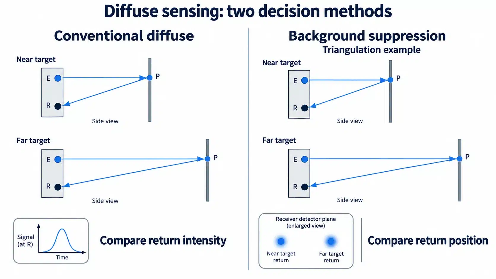
Background suppression is a form of diffuse sensing that uses distance discrimination to help reject the background. Conventional diffuse sensing relies on returned-light intensity. Compare them by checking target variation and target-to-background separation, not the sensing-range headline alone.

Quick Comparison: Background Suppression vs. Conventional Diffuse Sensing
Both arrangements send light toward a target and receive its reflection from the same side. Neither requires a separate reflector. In this comparison, conventional diffuse means intensity-based sensing without background suppression; BGS means diffuse sensing with background suppression.
| Comparison point | Conventional diffuse sensing | Diffuse sensing with BGS | What to check |
|---|---|---|---|
| Switching decision | Whether enough light returns to meet the detection threshold | Whether the return satisfies the sensor's distance-based detection conditions | The actual sensing function, not just the housing shape |
| Background influence | A background can produce a return that resembles a target | Returns beyond the intended cutoff can be rejected within the model's operating conditions | The nearest background with the target removed |
| Target variation | Changes in return strength can change the detection result | Distance discrimination helps, but surface and return quality still matter | Actual finishes, positions and orientations |
| Separation and near limits | Reliable operation depends on distinguishing the two optical states | Target/background separation and any near sensing limit must suit the application | The full target travel range and model-specific separation data |
| Adjustment | Sensitivity changes the level of return needed for switching | Fixed or adjustable distance criteria depend on the model | What the adjustment or teach procedure actually changes |
| Acceptance | Verify target detection and background rejection | Verify target detection and background rejection | Both states throughout the intended operating conditions |
Choose the simpler arrangement only when it separates the required states reliably. Choose BGS when distance provides a useful distinction that light intensity alone does not. The following sections explain how to judge that distinction before ordering a sensor.
How the Two Detection Methods Make the Switching Decision
Conventional Diffuse: Returned-Light Intensity
A conventional diffuse sensor emits light, collects part of the target's return and compares the received signal with a switching threshold. The target therefore participates in the optical system: its surface, size and orientation influence how much useful light reaches the receiver.
A sensitivity adjustment cannot identify which object produced that light. If the empty conveyor or machine surface returns enough light, the sensor may indicate a detection even after the intended part has gone. Reducing sensitivity can remove that unwanted response, but it also makes a weakly returning acceptable part harder to detect.
The useful question is whether one setting can satisfy both requirements across production variation. Establish that the least favorable acceptable target is detected, then remove it and check the actual background. If each adjustment fixes one state while breaking the other, continued sensitivity tuning has not solved the discrimination problem.
Background Suppression: Distance-Based Discrimination
BGS adds information about where the return originates. A common implementation uses triangulation: changing target distance shifts the position of the focused return on the receiver. The sensor uses that position to distinguish nearer target returns from returns beyond the intended cutoff.
This gives the sensor another basis for separating a target from a bright background. It does not create light from an undetectable target, nor does it remove the need for an appropriate optical arrangement. Other implementations, including time-of-flight designs, also exist; the BGS label alone does not specify the receiver design or its limits.
For selection, ask whether the candidate can distinguish the relevant distances with your actual surfaces. A product described only as “diffuse reflective” may or may not include BGS, so confirm the function in its documentation rather than inferring it from the enclosure or adjustment button.
Why Target-to-Background Separation Matters
Cutoff Distance and the Real Detection Window
The cutoff is the distance boundary used to separate the intended detection region from the background under specified conditions. Start with the farthest position at which the target must still be detected and the nearest position of the unwanted background. Measure from the reference specified by the sensor documentation.
A nominal cutoff between those positions is only a starting point. The installation needs enough usable separation for the selected sensor, the target variation and movement of the mounting arrangement. If the target sometimes moves into the same distance region occupied by an unwanted surface, a distance threshold alone cannot uniquely identify which object is present. Changing the viewing direction or controlling the target path may be more effective than choosing a longer-range sensor.
Also distinguish a taught reference from the resulting switch point. For example, the Q4X one-point BGS teach procedure places the switch point in front of the taught reference using that model's separation rules. This is a model-specific example, not a universal setup instruction. Read what your sensor teaches, then check where it actually changes state with the production target.
Color-Related Shift and Installation Variation
A switching boundary should not be treated as an infinitely thin, identical line for every surface. BGS documentation can specify different detection distances or required separation for different target reflectances. Where black/white shift is specified, inspect its definition and test conditions; it describes a difference under those conditions, not a general promise about every dark or glossy part.
Use those data to decide which samples deserve testing. If an approved product can arrive with several finishes, testing only the easiest finish does not establish the rest. Likewise, checking the nominal target location does not cover its farthest permitted position.
Keep the variables separate during setup. First hold the sensor and background fixed while changing target samples and positions. Then check permitted mounting and background variation. This makes a failure more informative: you can tell whether changing the part, moving the geometry or changing both caused the loss of separation. There is no universal minimum gap that replaces the model data and these checks.
When Conventional Diffuse Sensing Is Sufficient
Conventional diffuse sensing is a reasonable starting point when acceptable targets produce a clearly distinguishable return and the actual target-absent background does not trigger detection. A controlled target path and limited surface variation make that question easier to answer, but neither condition proves success by itself.
Use a repeatable setup check: place the most difficult acceptable sample at its least favorable required position, confirm detection, remove it, and confirm that the exposed background gives the opposite detection state. Repeat with other relevant finishes and orientations without retuning for each sample. A setting that works only after every product change is not a common production setting unless that changeover adjustment is part of the agreed process.
If the checks succeed with practical tolerance for normal variation, there may be no application reason to change sensing methods. If they fail, identify which condition is responsible before selecting a replacement. A background problem, an unstable part path and insufficient return from the target call for different corrective actions.
When Background Suppression Is the Better Starting Point
BGS is worth evaluating when the target and background are difficult to distinguish by return strength but occupy distances the candidate sensor can separate. Examples to investigate include parts passing in front of a machine surface or products whose changing appearance makes intensity-only adjustment unreliable. These are application possibilities, not claims of successful installations.
The choice depends on whether distance adds a dependable distinction. Document the target's allowed travel, the background location and any objects that may enter the field of view when the target is absent. Select a candidate whose stated operating conditions cover that arrangement, then challenge it with the actual samples.
BGS is not a reason to ignore a poor viewing position. If a bracket intrudes into the intended detection region, or the target can move behind the chosen cutoff, the sensor may be making a correct distance decision that is wrong for the machine's purpose. Improve the geometry or assess another sensing arrangement when no usable detection region can be established.
Conditions That Still Need Testing
Glossy, Dark, or Transparent Targets
A dark target may return too little useful light at a particular distance or angle. A glossy surface can direct its reflection differently as it moves. Transparency introduces another concern: the wanted object may not provide a distinct usable return, while light can also reach surfaces behind it. A generic BGS label is insufficient evidence that all these conditions are covered.
Test the variation that the machine actually permits. Rotate or tilt representative samples through their allowed positions instead of finding one favorable angle and treating it as the installation. Where orientation guidance is specified, follow the selected model's instructions; there is no mounting angle suitable for every glossy target.
If transparent material is central to the task, request explicit confirmation of the model and sensing mode intended for it. Do not extend the capability of a special clear-object mode to every BGS sensor. Similarly, check any near sensing limit before moving the sensor closer as a proposed fix.
Small Features, Edges, and Changing Angles
For a narrow feature or an approaching edge, examine where the light spot falls throughout the movement. Part of the illuminated region may fall on the target while another part falls beyond it. The resulting return depends on the geometry and sensor design; nominal housing size or a visible aiming spot does not establish the minimum detectable feature.
Use the smallest acceptable feature and the least favorable sideways position in the trial. Check the feature entering and leaving the field of view, including any permitted tilt. For triangulation-based models, the orientation of an edge relative to the optical arrangement can matter, so consult the mounting guidance rather than assuming every rotation of the sensor is equivalent.
The purpose is to identify a reproducible detection condition. If only a carefully centered sample works, improve the guidance or choose an optical arrangement matched to the feature before relying on that result in production.
Validate the Choice on the Actual Machine
Test Target-Present and Target-Absent Conditions
Use the final sensor position, representative parts and the actual background wherever practicable. Record the model, operating mode and adjustment so the result can be reproduced. Then work through both required states:
- Check acceptable targets. Test relevant surface variants at the nearest and farthest required positions, including allowed tilt and sideways movement. Confirm that each acceptable target is detected.
- Remove the target. Check the background and any machine surfaces exposed during a normal cycle. Include the nearest permitted background position and the finishes most likely to create an unwanted return.
- Repeat the transition. Pass the target into and out of the detection region through its actual path. Look for missed detections, extra changes of state or failure to return to the target-absent state.
- Check realistic operating variation. Include relevant changes in lighting, cleanliness and positioning within the documented limits. Test physically possible combinations, not an arbitrary collection of unrelated extremes.
- Retain the result. Record which sample and condition produced each observation. If the arrangement fails, change one setup variable at a time and repeat the affected checks before accepting the revised setting.
| Test condition | Required confirmation | Useful record |
|---|---|---|
| Acceptable target at a difficult position or finish | Target is consistently recognized | Sample identity, position, orientation and setting |
| Target removed, background exposed | Background is not accepted as the target | Background surface and nearest position |
| Target enters and leaves through its permitted path | Both transitions occur as required | Path, speed and any irregular transition |
| Normal operating variation | Both states remain distinguishable | Changed condition, observation and corrective action |
This is a validation plan, not a report of measured performance. Set the acceptance criteria for the actual machine before testing; a favorable demonstration with one sample is not a substitute for those criteria.

Confirm the Output at Operating Speed
After the optical checks, verify that the receiving input recognizes the required states while the equipment operates at the intended speed. Keep this separate from the static test: a stationary part establishes neither the available signal duration during motion nor the receiving system's ability to capture it.
Check the selected sensor's timing and output documentation together with the receiving input requirements. Observe the relevant input or event record, not just the sensor indicator. An optical detection that is not registered by the controller does not complete the machine's detection task.
If a failure appears only during motion, retain the speed, target spacing, output settings and receiver configuration with the test record. Diagnose that condition before changing the optical cutoff to compensate for a problem elsewhere in the detection chain.
Prepare the Information Needed for Model Selection
A useful model inquiry describes the detection point rather than asking only for “a BGS sensor” or a longer sensing range. Prepare:
- The target: material, dimensions, the feature to recognize, surface variants and acceptable orientation changes; provide representative samples where possible.
- The geometry: nearest and farthest target positions, background positions, mounting space and a sketch of the viewing direction.
- The process: target motion, required detection events and what the machine should do with the signal.
- The interface and environment: supply and output requirements, receiving input details, lighting, contamination, cleaning exposure and other relevant operating conditions.
- The acceptance requirement: which target-present and target-absent conditions must work, and what evidence will be retained from the trial.
Ask for the candidate model's applicable range, near limit, target/background separation information, surface-dependent switching data and setup instructions. Request clarification where a specification uses a reference target unlike the production part. A catalogue maximum distance alone does not answer whether the required states can be separated in your installation.
Use those details to select a candidate and agree a representative test. The right choice is the one that resolves the detection task under its actual conditions, with a setup that can be documented and reproduced.
Technical Sources
- OMRON — Overview of Photoelectric Sensors. Diffuse and distance-settable sensing principles and application selection factors. Undated web guide; accessed October 16, 2026.
- Baumer — Mounting of light barriers and diffuse sensors. Background separation, target-dependent distance variation and mounting orientation. Undated web guide; accessed October 16, 2026.
- ifm — Photoelectric sensor technology overview. Diffuse sensing, background interference and different BGS implementations. Undated web guide; accessed October 16, 2026.
- Banner Engineering — Q4X Stainless Steel Laser Sensor Instruction Manual. P/N 181483 Rev. P, September 10, 2025; one-point BGS teach description, p. 31. The cited setup example applies to that model and mode.