The sensor emits light
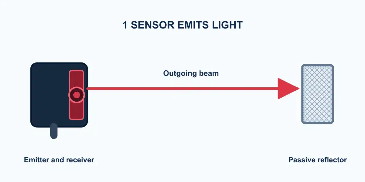
The emitter sends a beam across the monitored path toward a compatible reflector.

Sensor Terminology
Meaning, Working Principle and Applications
A retroreflective photoelectric sensor places its light emitter and receiver in one housing. A separate reflector returns the beam. When a target passes through this path and sufficiently reduces the returned light, the sensor detects the change.
Learn how it works →
It is a photoelectric sensor that points toward a reflector across the target path. The sensor emits light, and its receiver monitors the light returned by the reflector. A passing object is recognized when it causes the received light to change enough to meet the sensor’s detection threshold.
Unlike a through-beam setup, the emitter and receiver do not need separate powered housings on opposite sides. Unlike a diffuse-reflective sensor, a standard retroreflective setup uses a dedicated reflector rather than relying on the target to return light.

Detection is based on the amount of light returned from the reflector—not on the object touching the sensor.
The emitter sends a beam across the monitored path toward a compatible reflector.
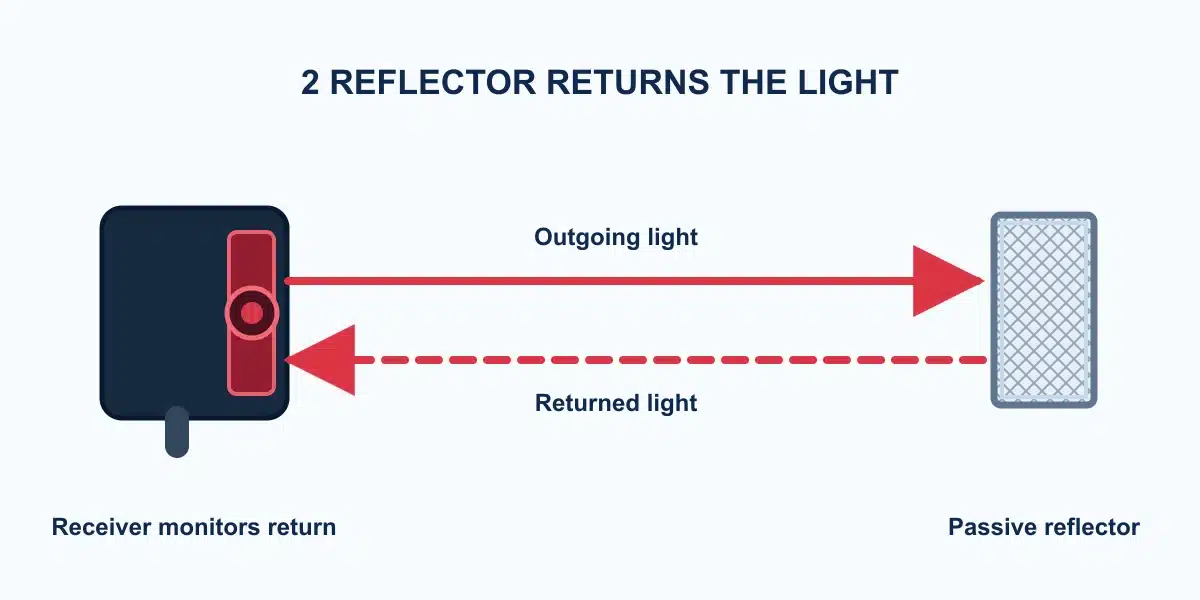
The reflector directs light back to the receiver in the same sensor housing. Alignment and a clean optical path help maintain a stable reference signal.

As the target crosses the path, less reflector light reaches the receiver. The sensor changes its configured output when its switching condition is met.
The opposite side needs a reflector, not a second powered receiver. This can simplify wiring where both sides of the path are accessible.
Conventional retroreflective models often reach farther than comparable diffuse-reflective models. Actual range depends on the exact sensor and reflector.
For suitable opaque targets, detection relies mainly on beam attenuation rather than light reflected directly from the target surface.
It can support package presence, passage and counting checks when target size, speed, alignment and controller timing are verified.
These are example use cases. The sensor and reflector still need to be tested with the actual target, travel path and environment.

Detect a box or part crossing the beam. Check the smallest item, gaps between items and line speed.

Confirm product presence at a transfer or positioning point with a clear path to the reflector.

Detect suitable opaque containers. Clear bottles require a model specified for transparent-object detection and a real-sample trial.
The right arrangement depends first on mounting access and the optical behavior of the target. Range descriptions are relative tendencies, not interchangeable product ratings.
| Item | Retroreflective | Through-beam | Diffuse-reflective |
|---|---|---|---|
| Optical arrangement | Emitter and receiver in one housing; separate reflector | Separate emitter and receiver face each other | Emitter and receiver in one housing; target returns the light |
| Detection event | Target reduces light returned from reflector | Target interrupts light reaching receiver | Target changes light reflected into receiver |
| Opposite-side mounting | Reflector required | Powered receiver or emitter required | Not required |
| Range tendency | Often longer than conventional diffuse; model dependent | Often the longest of these arrangements; model dependent | Often shorter and more target-dependent; model dependent |
| Key check | Reflector compatibility, alignment, shiny or clear target | Two-sided access, alignment and target size | Target reflectance, background and distance |
Use a reflector size and type supported by the exact sensor model. Check the published operating range with that reflector and leave practical alignment margin.
Confirm that the smallest target crosses enough of the beam at the real mounting distance. Inspect brackets, vibration, dirt and access for alignment or cleaning.
Mirror-like objects can return light toward the receiver; clear objects may transmit too much light. Consider a suitable polarized or clear-object model and test worst-case samples.
Both detect a target crossing a light path. Retroreflective sensing puts emitter and receiver in one sensor housing and uses a separate reflector. Through-beam sensing places the emitter and receiver in separate housings on opposite sides of the path.
Some purpose-designed clear-object retroreflective sensors can, but a standard model should not be assumed reliable. The bottle material, wall thickness, shape, label and motion can all affect the returned signal; test the actual sample and model.
The sensor needs an adequate, stable return from a compatible reflector. Its size, distance, orientation and cleanliness affect the received light. The rated range may be specified with a particular reflector, so check the datasheet.
A mirror-like target can return light toward the receiver even while it blocks the normal reflector path. A polarized or mirror-surface-rejection design may help, but the actual target and geometry still need testing.
No. Detection changes the sensor’s switching state, but whether the electrical output is ON depends on its light-on/dark-on configuration and output circuit. Check the exact model and controller input.
Share the target material, dimensions, sensing distance, reflector position and controller input. XSZ can help narrow the options for a model-specific test.