
Cylindrical metal housing
Threaded format for brackets and adjustable mounting positions.

Sensor Terminology
Principle, Sensing Distance, Materials and Applications
A capacitive proximity sensor detects a change in capacitance near its sensing face. It can respond to conductive targets and suitable non-metal materials, making it useful for presence checks and selected point-level tasks. The actual switching distance depends on the target, mounting and sensor setting.
Explore How It Works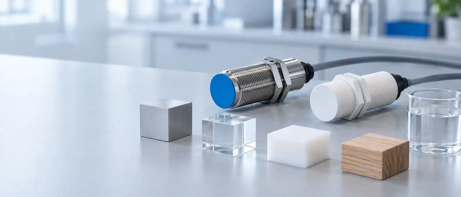
It is a non-contact sensor that detects a change in capacitance between its sensing electrode and the surrounding target or reference. As an object approaches, its size, distance and electrical properties influence that change. The sensor's electronics compare the response with a switching threshold.
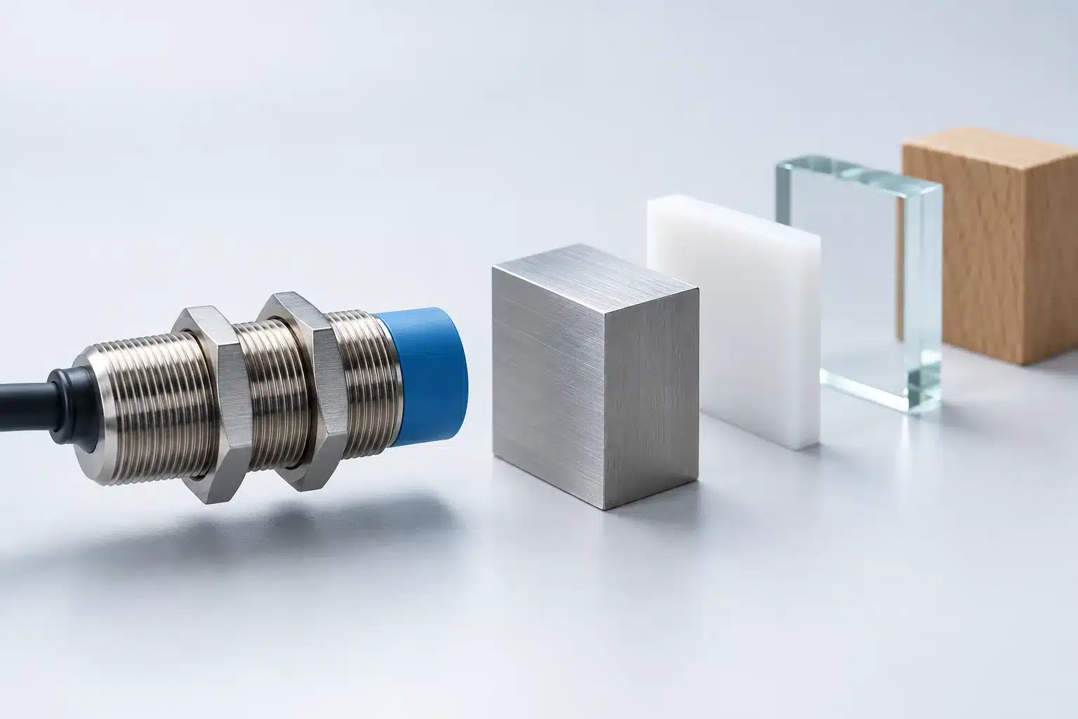
Unlike an inductive proximity sensor, which is generally used for metal targets, a capacitive type may detect plastics, glass, liquids, wood or granular materials as well as metal. “May detect” is important: the usable range and stability must be checked with the actual material and installation.
The sensing electrode creates an alternating electric field near the active face. A nearby target changes the field's capacitance. Internal electronics evaluate that change and switch the configured output when the response crosses a threshold.
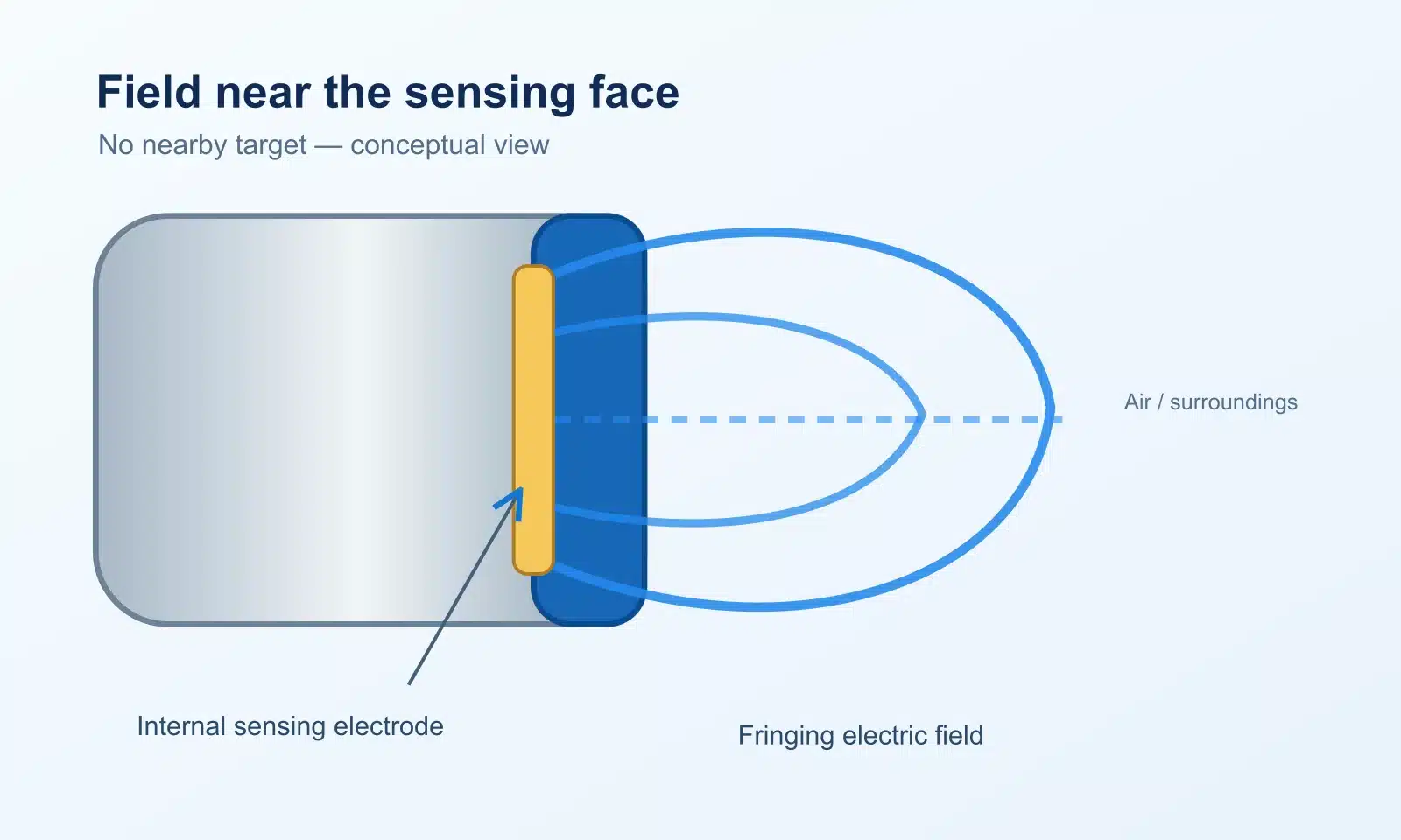
The active electrode interacts electrically with its surroundings.
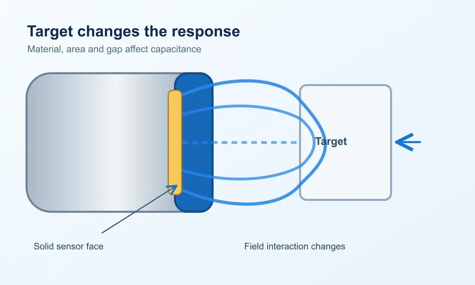
Target material, area and distance alter the measured capacitance.
The circuit distinguishes the target response from its set baseline.
The output changes state according to the model's NO/NC setting and wiring.
The electrical output type—such as NPN, PNP, two-wire, NO or NC—is a separate specification from the capacitive sensing principle.
The housing changes how a sensor fits the machine; it does not by itself define the sensing distance or output circuit. Confirm each model's mounting, environmental and electrical specifications.
Threaded format for brackets and adjustable mounting positions.

Alternative mounting footprint where a threaded body is impractical.

Selected for a particular mounting or media environment when rated for it.

Useful on some vessel walls or space-limited equipment; model dependent.
A rated sensing distance is established under the manufacturer's stated test conditions, often with a defined metal reference target. It is not a promise that every plastic, liquid or powder will switch at the same gap.

| Condition | Practical implication |
|---|---|
| Reference target | Use the datasheet's target and mounting basis. |
| High-permittivity target | Often produces a stronger response than a low-permittivity target of similar geometry. |
| Low-permittivity target | May require a shorter gap or sensitivity adjustment. |
| Through-wall sensing | Depends on a suitable non-metal wall, medium, thickness and model. |
| Changing environment | Recheck margin with condensation, buildup or material variation. |
These are qualitative checks, not universal correction factors. Compare the exact sensor's data with application tests.
Mount the sensing face and set the switching threshold with both the target-present and target-absent states available. Leave enough margin that normal changes in position or environment do not cause unwanted switching.
Use the exact model's flush or non-flush instructions and required clearance from nearby metal.
Check the smallest or least responsive target, not only a metal test piece or a full vessel.
After setting sensitivity, verify that walls, residue, moisture and background objects do not trigger the output.
For sensing through a vessel wall, select a compatible sensor and non-metal wall arrangement. Do not assume a standard capacitive sensor can detect a medium through a metal wall.
These are possible target classes, not a universal compatibility list. Detection must be confirmed at the required distance with the actual size, moisture state and mounting arrangement.

Conductive target; still verify geometry and setting.

Response varies by resin, thickness and size.

Container or target geometry affects response.

Medium and vessel wall both matter.

Moisture can change the switching margin.

Bulk density and buildup require testing.
Use the sensor only after confirming the target, vessel or machine geometry and the necessary output behavior.
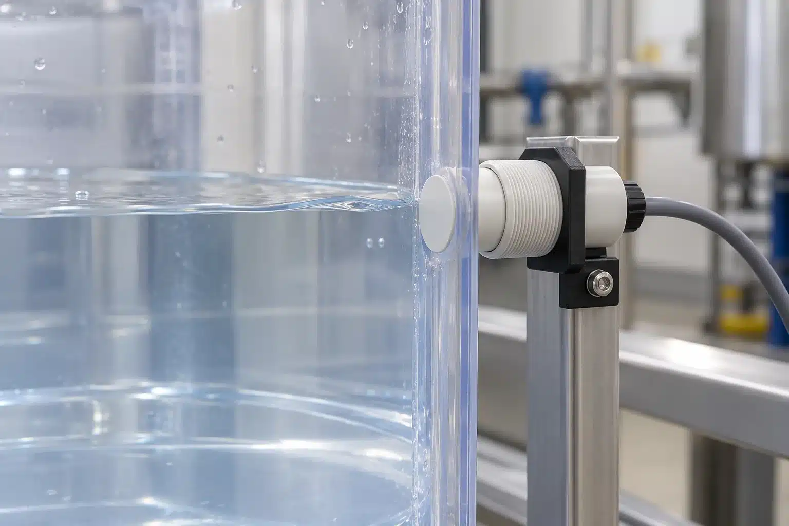
Detect a selected fill point, sometimes through a compatible non-metal vessel wall.
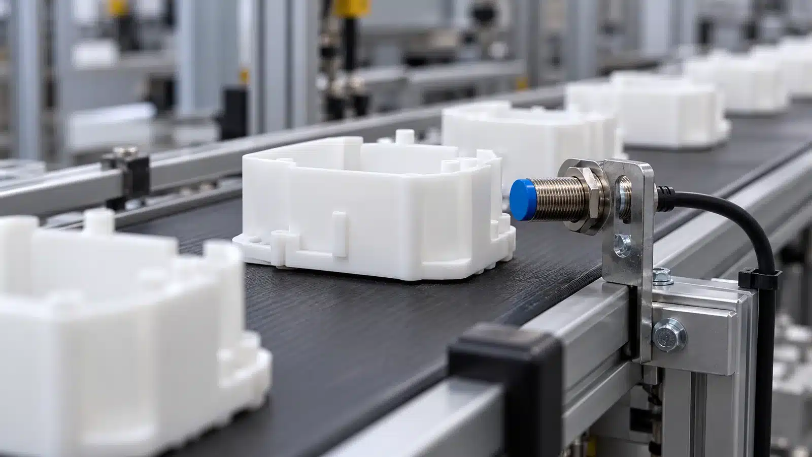
Check whether a non-metal component enters a defined sensing zone.
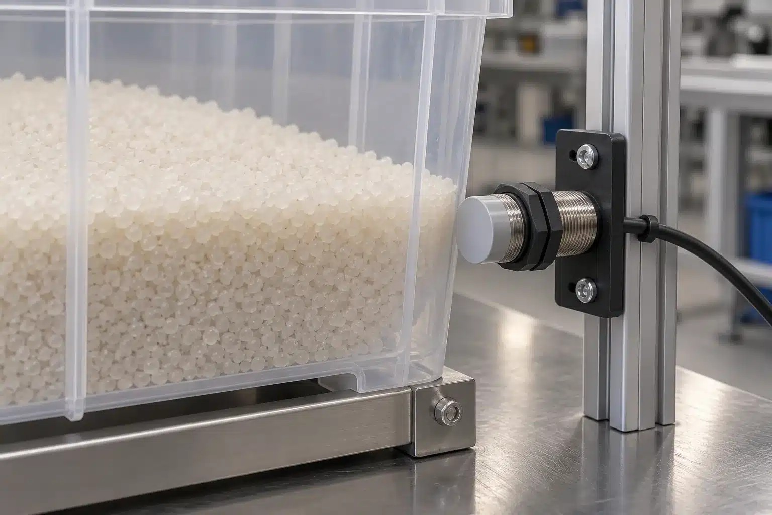
Detect a suitable medium inside a non-metal container after wall and residue tests.

Switch at a point in a hopper or vessel when the bulk material responds reliably.

Detect a stack edge or position with material-specific adjustment.

Sense selected packaging materials where optical contrast is unreliable.
Yes, many models can respond to both. For non-metal targets, the usable distance depends on the material's electrical properties, size and distance. Check the exact target in the intended installation.
Some capacitive sensors are designed for point-level detection through non-metal walls. Success depends on the liquid, wall material and thickness, mounting, nearby metal and calibration. Follow the selected model's application instructions.
The published distance is defined under the manufacturer's test conditions. Actual switching distance changes with target properties, geometry, installation and sensitivity; test the required worst-case target and both switching directions.
A capacitive sensor evaluates a change in capacitance and may detect suitable non-metal materials. An inductive sensor detects metal through electromagnetic induction. Neither method is automatically best for every application.
No. Adjustment methods and ranges are model-specific. If the model supports adjustment, follow its manual and confirm the target-present and target-absent margins after setup.
Check nearby metal, buildup, moisture, wall effects, sensitivity and wiring. Test the sensor in its final mounted position before changing settings; inspect the device manual for the required clearances.