

What Is a PNP Sensor?
A PNP sensor is a sensor with a PNP transistor switching output. In a typical three-wire DC circuit, its ON output connects the positive supply side to the external load or input. Current leaves the output, passes through that load or input, and returns to 0 V. This is a sourcing output.
PNP identifies the electrical output, not the detection technology. An inductive, capacitive or photoelectric sensor can be offered with PNP output. PNP also does not mean “normally open”: a PNP variant may be NO, NC or selectable according to its model.
A positive-side transistor switch conducts when ON.
Current leaves the sensor output toward the load or input.
NO/NC determines when the output turns ON, not its current direction.
How Does a PNP Sensor Work?
Think of the output as a switch on the positive side of a load. When the PNP output turns ON, it completes a path from +V through the output and the connected load or PLC input to 0 V. This is high-side switching.
For a typical PNP normally open (NO) sensor, no target leaves the output transistor OFF and detection turns it ON. With a compatible load, an ON output rises toward the positive supply, subject to the device's voltage drop. An OFF transistor does not define a universal measured output voltage; the external input or load circuit affects that reading.
Swipe to read the diagram →
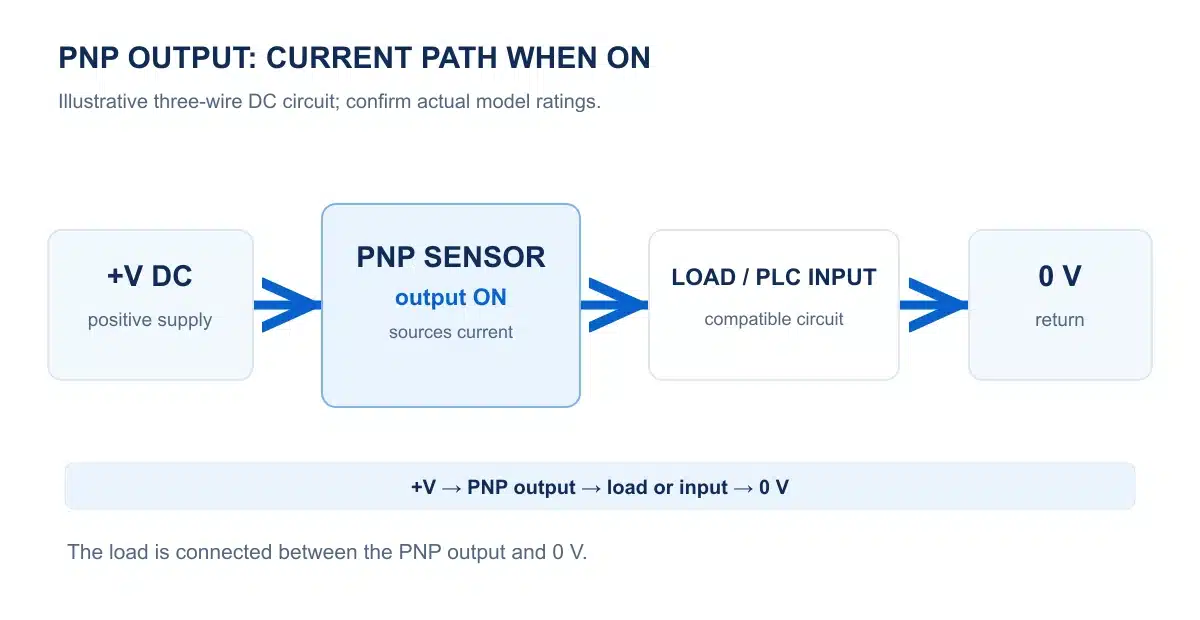
Typical PNP NO output state
| Target condition | Output transistor | What the compatible load sees |
|---|---|---|
| No target | OFF | No intentional source path from the output; the input circuit determines the output-node voltage. |
| Specified target detected | ON | Current can flow from +V through the sensor output and the input/load to 0 V. |
How to Wire a PNP Sensor to a PLC
For a typical three-wire DC PNP model, brown (BN) connects to the specified +V supply, blue (BU) to 0 V, and black (BK) to a compatible PLC digital input. The input circuit needs a return path toward 0 V so current supplied by the sensor can flow when its output is ON.
In this illustrative circuit, the PLC input group's COM− connects to 0 V. When the PNP output turns ON, current flows from +V through the sensor's black output and the input circuit to COM−. Module labels and terminal arrangements vary; check the actual PLC input wiring diagram before connecting.
Swipe to read the diagram →

| Wire | Connection | Function |
|---|---|---|
| Brown (BN) | +V DC | Sensor power + |
| Black (BK) | PLC digital input | PNP output |
| Blue (BU) | 0 V DC | Sensor power − |
| PLC COM− | 0 V DC | Input current return in this example |
PNP vs NPN Sensors
The main difference is the ON-state current path. A PNP output sources current from +V to a load or compatible input; an NPN output sinks current from a positively supplied load or input toward 0 V. Select the output by the actual controller input circuit, not by region or wire color alone.
Swipe to read the diagram →
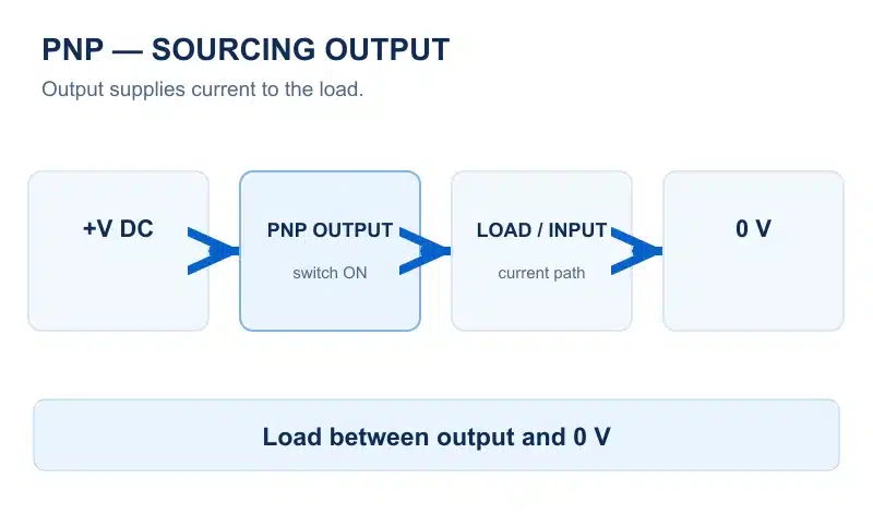
Swipe to read the diagram →

| Item | PNP | NPN |
|---|---|---|
| ON-state action | Sources current | Sinks current |
| Load connection | Output to 0 V | +V to output |
| Typical output voltage under load | Near +V, allowing for voltage drop | Near 0 V, allowing for residual voltage |
| Typical PLC input pairing | Compatible current-sinking input | Compatible current-sourcing input |
PNP NO vs PNP NC
PNP specifies the ON-state sourcing direction. Normally open (NO) and normally closed (NC) specify the output-transistor state in the maker's normal no-target condition. They are independent choices.
Swipe to read the diagram →

Swipe to read the diagram →

| Target condition | PNP NO transistor | PNP NC transistor |
|---|---|---|
| No target | OFF | ON |
| Target detected | ON | OFF |
How to Identify a PNP Sensor
Do not identify a PNP output from the number or color of wires alone. Verify the exact model variant and its output circuit.
- Check the full model code and label. Confirm the maker's suffix key; product families often include more than one output variant.
- Read the datasheet output specification. Look for “PNP transistor” or “sourcing output,” plus the NO/NC option, supply range and rated load current.
- Trace the manufacturer's circuit. A typical PNP load sits between output and 0 V. Confirm the module input common and pinout before wiring.
Common PNP Sensor Wiring Problems
If an input never changes or reports an unexpected state, inspect the complete circuit rather than assuming that the sensor is faulty.
The PLC input is not arranged to accept sourced current. Check its common/reference connection and supported input type.
Brown, blue and black are common conventions, not proof of a particular model's pin assignment. Confirm the rated supply and exact diagram.
Verify output current, voltage drop, leakage, PLC input thresholds and any external load against both datasheets.
A PNP NC output can be ON without a target. Check the specified normal condition and whether the PLC program inverts the input.
Frequently Asked Questions
What does PNP mean on a sensor?
It identifies a positive-side transistor switching output. When ON, the output sources current from the supply to a compatible load or input connected toward 0 V.
Does PNP mean normally open?
No. PNP describes the ON-state output circuit. NO or NC describes whether the transistor is OFF or ON in the specified no-target condition.
Can a PNP sensor connect to any PLC input?
No. The input must accept the sensor's sourced current and meet its voltage, current and common-reference requirements. Use both manufacturers' diagrams to confirm compatibility.
Is a PNP output always exactly +24 V when ON?
No. The supply may not be 24 V, and the output has a model-dependent voltage drop under load. Check the datasheet and measure in the intended circuit.
Can I replace an NPN sensor with a PNP sensor?
Not as a drop-in change unless the controller input and wiring support the opposite current direction. Recheck the full model, NO/NC behavior, power supply and input circuit before replacement.