
Shielded vs. Unshielded Inductive Sensors: Mounting and Sensing Distance
Start with a shielded, flush-mount inductive sensor when the sensing face must sit level with surrounding metal. Consider an unshielded, non-flush design when its required metal-free space is available and a comparable design offers useful additional sensing distance. The choice depends on the selected model’s installation rules and the actual target, rather than range alone.
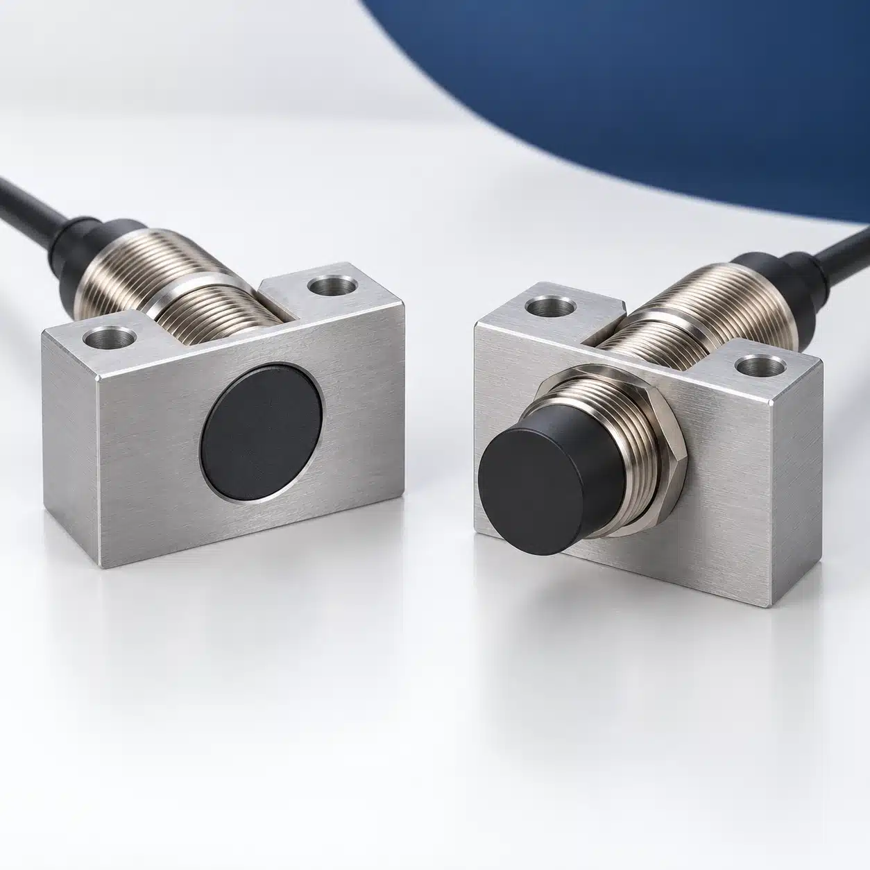
Quick Comparison: Shielded vs. Unshielded Inductive Sensors
Use this comparison to shortlist a mounting style. The individual sensor’s installation drawing determines whether it fits the detection point.
| Selection condition | Shielded / commonly flush-mount | Unshielded / commonly non-flush |
|---|---|---|
| Surrounding mounting metal | Designed for a specified flush arrangement | Requires a defined metal-free area around the sensing head |
| Sensing-distance trade-off | Often a compact mounting choice within comparable designs | May offer more distance within comparable designs, with additional clearance requirements |
| Space to allow | Check permitted side metal, face position and opposing metal | Include the required head projection and surrounding clearance |
| Nearby sensors | Review the model’s spacing requirements | Review the model’s spacing requirements; free space for mounting alone is insufficient |
| Final selection check | Confirm detection and reset with the actual target in the final mounting | Confirm both the metal-free installation and detection/reset with the actual target |
The useful comparison is the distance available after the installation requirements are satisfied. A higher nominal range does not make an unsuitable mounting arrangement acceptable.
What Shielding Changes at the Sensing Face
An inductive sensor produces an alternating electromagnetic field at its sensing face. A metal target interacts with that field; in a common oscillator-based design, induced eddy currents draw energy from it. The electronics detect the resulting change and switch the output. Surrounding machine metal can therefore matter as well as the intended target.
Here, shielded describes the sensing-head construction. It does not mean a shielded cable, a particular ingress-protection rating or immunity to external electromagnetic interference. Those are separate product characteristics.
Shielded Sensors and Flush Mounting
A shielded design has metal around the sides of the sensing coil, concentrating the useful field toward the front. This allows the specified flush arrangement: the sensing face can sit level with the surrounding mounting metal, subject to the model’s instructions.
That can be useful when a machine designer wants to avoid a projecting sensing head. However, metal beside the head and metal directly in front of it occupy different positions. A permitted side mounting does not make a front plate invisible to the sensor. Flush mounting also does not automatically permit recessing the face below a metal surface.
Unshielded Sensors and Metal-Free Clearance
An unshielded head has a more laterally extended sensing field. Within comparable constructions, this can provide additional sensing distance, but nearby mounting metal can also influence the sensor. If the head is enclosed too closely, that metal can affect the detection condition before the intended target arrives. This is often described as predamping and can lead to false triggering.
The specified metal-free area is therefore functional space, not simply room for assembly. When assessing a bracket, include the volume around the head that the drawing requires to remain clear. A sensor that fits through the mounting hole may still be unsuitable for that bracket.
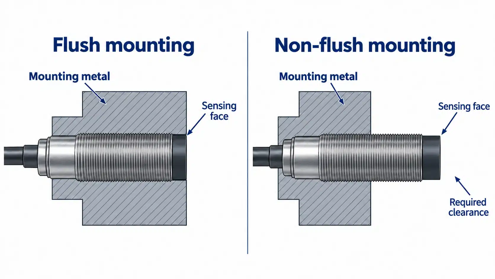
Read the Mounting Conditions Before Comparing Distance
Begin with a sketch showing the sensing face, fixed metal and complete target path. Then compare that sketch with each candidate’s mounting drawing. This separates physical fit from a permitted sensing environment.
Side Metal, Recesses, and Opposing Surfaces
Check three relationships separately: metal around the sides, the face position relative to the mounting surface, and metal opposite the face. A drawing that permits one relationship does not necessarily permit the others.
For example, if a protective metal lip extends beyond the sensing face, the proposed installation is recessed rather than simply flush. If a fixed steel member sits opposite the face, it also needs consideration when the intended target leaves. The relevant question is whether the sensor can distinguish the required target-present and target-absent conditions with all that metal still in place.
Do not approve the arrangement from a generic diameter-based rule. Mark the actual distances and installation material on the sketch, then obtain the selected model’s permitted values. If the drawing does not cover the proposed recess or opposing structure, resolve that uncertainty before ordering.
Adjacent Sensors and Mutual Interference
Nearby inductive sensors introduce another installation constraint: their active fields can interact. A metal-free zone around one head does not establish that two powered sensors may be placed arbitrarily close together.
Review the required spacing for the actual arrangement, including side-by-side or face-to-face installation. During commissioning, observe the required states with the neighboring sensors operating as they will in the machine. A check made with only one sensor powered can miss a condition created by the complete installation.
If the layout cannot meet the documented spacing, discuss an appropriate arrangement or a model with explicitly supported interference-control features. Shielded construction alone is not evidence that the proposed spacing is acceptable.
Quasi-Flush and Extended-Range Designs
Some designs are described as quasi-flush or semi-flush, with their own projection and clearance requirements. Extended-range products can also have installation conditions that vary with the surrounding material. A general flush/non-flush label cannot capture every such case.
When comparing these products, keep the range specification and its installation instructions together. If a candidate needs a different face position in the intended metal, include that position in the mounting assessment. An apparent range advantage may be less useful when the required position cannot be accommodated.
Do not identify the permitted mounting solely from the color, shape or apparent projection of the sensing cap. Confirm it from the exact product documentation.
Compare Sensing Distance Under the Right Conditions
Once the mounting is feasible, compare what the distance figures mean for the detection task. A catalog value and a production switching position answer different questions.
Nominal Range, Operating Distance, and the Actual Target
Nominal sensing distance describes performance under defined reference conditions. It is a comparison parameter, not a complete statement of the distance available for every metal object. Read the manufacturer’s definitions of operating or assured distance and the conditions attached to them.
The production target can differ from the reference target in material, size and shape. A narrow edge, a curved part or a small feature may interact with the sensing field differently from a reference plate. Some designs address material differences differently, so one correction factor cannot be applied across all inductive sensors.
Define the target’s allowed position range before choosing the nominal distance. For a presence check, the candidate needs to recognize the difficult target at the largest permitted gap while also producing the correct absent state. Selecting the highest range number without considering both states leaves half the task untested.
Use documented model conditions and representative samples to assess that operating space. Do not turn a general percentage of nominal range into a universal installation allowance or an XSZ performance guarantee.
Axial Approach, Sideways Passage, and Reset
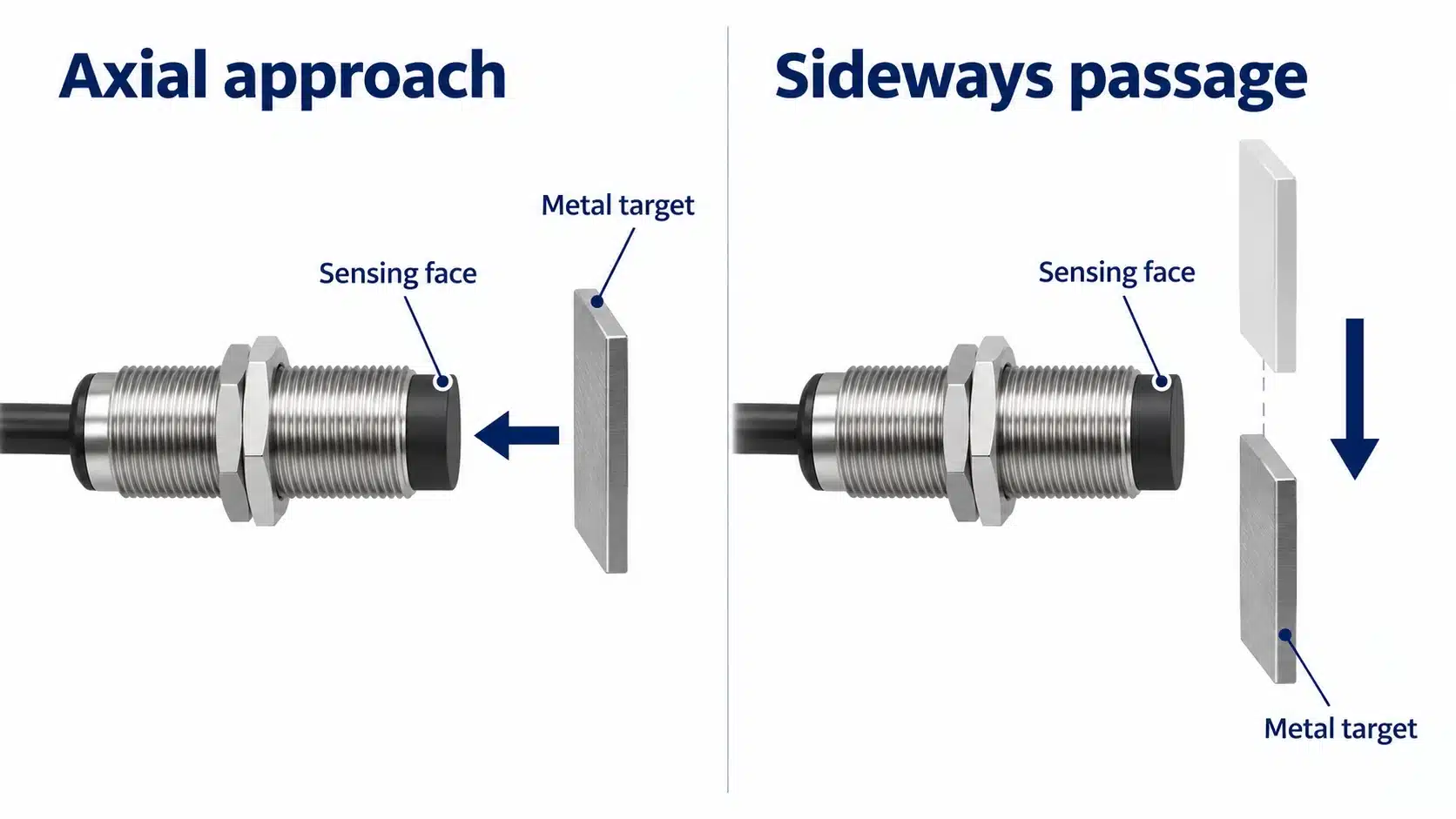
With an axial approach, the target moves toward the sensing face. With sideways passage, the target crosses in front of it. In the latter case, the switching position depends on both the face-to-target gap and the target’s lateral position. One axial distance figure cannot tell you exactly where a passing edge will trigger.
Hysteresis is the difference between the operate and release positions. A repeated detection task must provide enough target movement for both transitions; reaching the detected state once does not prove that the next target can be distinguished.
For a passing-part application, evaluate the leading and trailing portions of the actual target path. For a reversing mechanism, evaluate approach and withdrawal along the permitted motion. Record where detection begins and where the sensor returns to the required state. The result should describe the accepted setup, rather than become a new universal sensing-distance claim.
Choose the Mounting Style for the Detection Point
Choose by the constraint that cannot readily change. If the sensing face must remain level with nearby machine metal, first assess candidates explicitly permitted for that flush arrangement. Compare their documented distance conditions with the actual target and its position variation.
If more separation from the target is needed and the machine can provide the required metal-free area, an unshielded candidate may be worth evaluating. Include its head projection in the mechanical layout before treating the additional distance as useful. If the installation cannot provide that space, choose another documented arrangement instead of enclosing the head and hoping that the nominal range compensates.
If neither candidate can distinguish the required states in the available space, revisit the sensing position, target feature or mounting geometry. Changing the sensor label alone may not resolve the detection problem.
For a replacement, the same thread size establishes only part of the mechanical fit. Match the permitted mounting, actual target behavior and electrical interface separately. Supply, output circuit, switching function and receiving-input requirements must remain compatible; flush/non-flush terminology does not specify them.
Validate the Installed Sensor Before Ordering
Use a controlled evaluation to confirm the shortlisted arrangement. The following checks are engineering recommendations for ordinary process detection, rather than reported XSZ test results. Follow the machine’s safe commissioning procedures, isolate hazardous movement before making adjustments, and keep every test within the product’s documented limits.
Check Target-Present and Target-Absent Conditions
- Define the two required states. Identify the feature that must be detected and what remains near the sensing face when it leaves. Establish the expected output and receiving-input state for each condition.
- Build the permitted mounting. Use the intended bracket material, face position and documented clearances. Include fixed opposing metal and the final neighboring-sensor arrangement.
- Challenge the present condition. Use representative difficult targets at the allowed extremes of gap and alignment. Confirm that the required feature is detected throughout its permitted position range.
- Challenge absence and reset. Remove or withdraw the target through the actual path. Confirm that remaining machine metal does not prevent the required return state, and repeat the movement to check that both transitions remain distinguishable.
- Confirm the complete signal path. Check the sensor output and the receiving controller during the intended operating cycle. An indicator change alone does not establish that the receiving input recognizes the required event.
- Retain the accepted conditions. Record the exact model, mounting sketch, target details, tested position range, controller settings and observed results. Review the selection if a later change alters those conditions.
If the arrangement only works after moving the sensor outside its permitted mounting conditions, treat the evaluation as unresolved. Correct the installation or assess another candidate before accepting it.
Information to Provide for Model Selection
Give a supplier enough information to evaluate the detection point, rather than requesting only a thread size and nominal range:
- Target material, dimensions and the specific feature to detect, with representative samples where available.
- Minimum and maximum face-to-target gap, approach direction, lateral movement and required reset position.
- A mounting sketch showing material, recesses, head projection, opposing metal and neighboring sensors.
- Operating cycle and receiving-controller requirements, including supply, output type and switching function.
- Relevant environmental conditions and the acceptance checks the proposed model must satisfy.
Use the XSZ inductive proximity sensor category as the product-family starting point, then confirm the exact candidate’s mounting drawing and applicable specifications. Final selection should connect the model to the documented installation and sample checks, rather than rely on the shielded or unshielded label alone.
Technical Sources
- OMRON — Proximity Sensors: Explanation of Terms. Shielded/unshielded construction, sensing distance and hysteresis.
- ifm — Compact Inductive Sensors: Installation Guidelines. Flush/non-flush mounting and surrounding-metal influence.
- Pepperl+Fuchs — Inductive Sensors and Connectivity: Basic Training. Reference conditions, target effects and mounting terminology; printed pages 10–20.
- Balluff — Basics and Installation: Inductive Sensors. Approach direction, distance definitions and design-specific installation conditions; printed pages 2 and 9–13.