
How Fork Sensors Detect Small Parts in Automated Equipment
An optical fork sensor detects a small part when the part, or a feature on it, passes through the light path between the sensor's two arms. The resulting change in received light changes the sensor's electrical output. Automated equipment uses that output to confirm presence, locate a moving feature, or register a passing part.
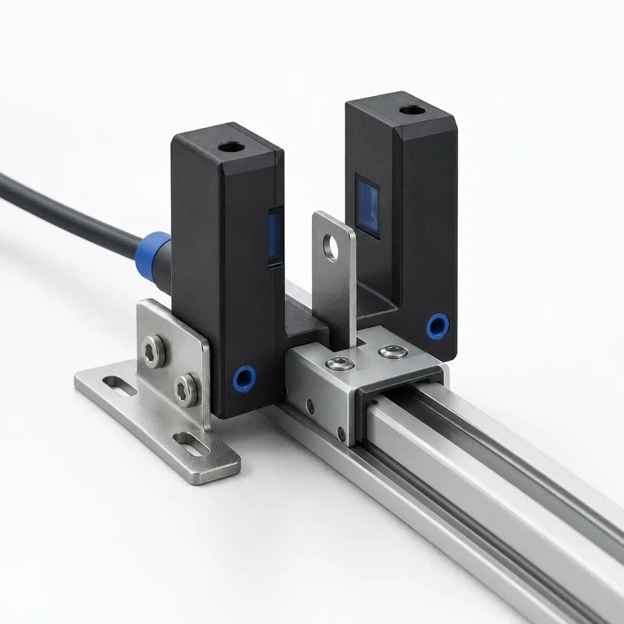
Reliable detection depends on what crosses the beam and how the machine interprets the signal. The intended feature must create a distinct optical change throughout its allowed movement. For counting, the space between successive parts must also produce a distinguishable clear interval, and the controller must capture the resulting transitions. A sensor can detect a stationary sample successfully while the complete machine still misses or duplicates counts.
Detection Sequence at a Glance
- Position: The required part feature enters the sensing path.
- Light: The receiver sees a change between clear and obstructed conditions.
- Output: The sensor switches according to its configured operating logic.
- Machine event: The controller interprets the signal as presence, position, or a count.
How a Fork Sensor Turns a Passing Part into a Signal
The Fixed Emitter–Receiver Path
A photoelectric fork sensor, also called an optical slot sensor, places the emitter and receiver opposite each other in one housing. The emitter sends light across the opening toward the receiver. A target passing through that path changes how much light arrives. This article concerns that optical arrangement; the shape of a housing alone does not establish its sensing principle.
Keeping both optical elements in one housing fixes their alignment relative to each other. The machine builder does not have to mount and aim a separate receiver across the equipment. However, the housing does not control the trajectory of the part. The sensor can be internally aligned while a small pin, tab, or edge passes above or beside its beam.
The installation therefore has two separate requirements: sufficient clearance for the moving assembly, and a sensing path that intersects the feature of interest. A drawing that shows only the part fitting inside the opening does not establish that the feature crosses the optical axis. Mark the beam location on the mechanical layout and consider the full permitted movement, including tilt and lateral play.

From Beam Interruption to an Output Change
The sensor's electronics evaluate the received light and switch the output when the relevant operating condition is reached. The output represents the sensor's interpretation of the light path. It does not describe the object's identity or automatically explain why the light changed.
With dark operation, the output is active when the beam is interrupted; with light operation, it is active when the beam is clear. The exact operating mode and available settings depend on the model. Separately, an NPN or PNP output determines the electrical interface to the receiving circuit. Choosing an output circuit does not, by itself, specify whether the machine should treat an active signal as “part present” or “part absent.”
For a presence check, the machine may read the input state at a defined point in its cycle. For a count, the program may use a particular transition, such as the change from clear to blocked. That event definition matters: a part entering and then leaving the beam normally creates two transitions. Counting both without a deliberate reason can record two events for one passage.
What the Sensor Must Detect on a Small Part
Part Presence, a Feature, or a Passing Edge?
Start with the physical distinction the machine needs to make. Detecting a complete part in a guide is different from checking a thin flange on that part. Both may be described as small-part detection, but they place different demands on the optical arrangement.
If the task is simple presence detection, a consistent solid area of the part may provide the clearest interruption. If the task is to identify a feature, position the beam where the acceptable and unacceptable parts actually differ. Detecting a large body section cannot establish whether a small protrusion elsewhere is present.
Edge detection asks a different question again: at what position does the transition occur? The useful result is the relationship between that transition and the machine's required position. Changes in orientation or in the edge presented to the beam can move the switching point, even when the sensor continues to detect every part.
This is why the overall dimensions on a part drawing are not enough. Identify the smallest relevant projected feature at the beam, the orientations it can take, and the distinction that the output must preserve. A larger feature elsewhere on the component cannot compensate for missing the feature the process actually needs to inspect.
Beam Coverage, Opacity, and Target Position
The slot opening describes available mechanical space. It does not state the smallest feature the optics can resolve. Minimum-object specifications have their own test conditions, which may include target shape, position within the opening, sensitivity setting, and movement during the test. Those conditions must be understood before comparing the stated capability with a production part.
A feature that covers enough of the sensing path in one position may only graze it after the part tilts. The received-light change may then be too small or too variable to produce the intended output consistently. Locating the beam through a stable section of the feature is often more useful than proving that one carefully held sample can just trigger the sensor.
The target's optical behaviour also matters. An opaque plastic component can interrupt light even though it is not metal. A translucent component may transmit enough light to make the distinction less clear. Its appearance to a human observer is not sufficient evidence of its behaviour with the sensor's light source. Use the actual material, colour variants, thicknesses, and orientations that will occur in the machine.
For fork sensor small part detection, the practical question is whether the intended present and absent conditions remain distinguishable. If adjusting sensitivity helps detect a thin feature, also check the empty path and the permitted target variations. A setting that produces an output for one sample is not yet evidence of a usable operating margin.
Where Fork Sensors Fit in Automated Equipment
Guided Part Feeding and Counting
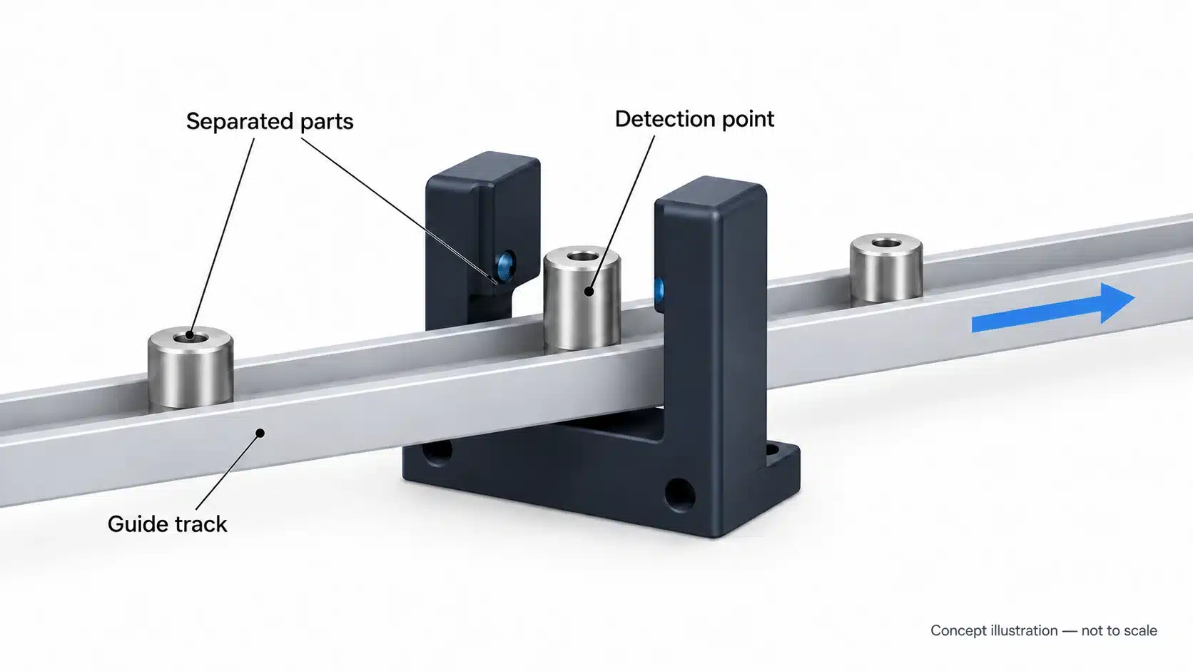
A guided feed can make fork sensing useful because the track constrains where each part passes the beam. The guide performs a mechanical job; the sensor reports the optical event at a chosen point. Reliable counting requires both jobs to work together.
Consider a hypothetical feed of small fasteners. If each fastener crosses the same sensing point with a clear space behind it, the output can provide a distinct event for each passage. If the fasteners bunch together, the sensor may correctly report one continuous obstruction. Replacing it with a faster sensor will not create an optical gap that does not exist.
The detection point should therefore be chosen with part separation and trajectory in mind. A point downstream of a mechanism that separates the parts may provide clearer events than a crowded upstream section. Where a part can bounce or rotate, examine whether its motion carries the same feature across the beam more than once. The aim is a repeatable relationship between a physical passage and the event the controller counts.
This arrangement can support a machine decision such as “a part has passed this point.” It cannot independently prove that the part subsequently reached the intended nest. If arrival at the next station is the requirement, that location needs its own suitable confirmation or a validated relationship between the two events.
Carrier Flags and Assembly-Position Confirmation
Sometimes the workpiece should not pass between the fork arms. A flag attached to a carrier, slide, or fixture can instead cross the beam to indicate a repeatable mechanical position. This can be useful where the machine offers a controlled flag path but the workpiece has an awkward shape or changes between production variants.
The meaning of that signal must remain precise. A flag on an empty carrier can still trigger the sensor. It confirms the position of the carrier feature, not the presence of the part it was supposed to transport. Likewise, a fixture reaching a position does not by itself prove that an assembly operation succeeded.
For a direct part-presence check at an assembly station, the target must distinguish a loaded fixture from an empty one. Check whether the fixture itself blocks the same path. If both conditions create the same optical state, the sensor has no information from which to distinguish them. Move the sensing point to a meaningful feature or use another suitable detection arrangement rather than trying to solve that ambiguity in software alone.
Why Separate Parts Do Not Always Produce Separate Counts
The Target Must Block the Beam—and the Gap Must Clear It
A stream of parts produces a useful counting signal only when the optical states alternate in a way the system can resolve. The part must interrupt the light sufficiently, and the gap must restore enough light for the output to reset before the next event.
Two parts can be physically separate without creating a usable clear interval at the sensing point. Their projected shapes may overlap the beam, or the gap may pass too quickly for the selected sensor and input arrangement. In either case, the controller may receive fewer distinct events than the number of parts passing through the machine.
The reverse problem is possible with a shaped part. A hole, notch, or change in orientation can expose the receiver during one passage and then obstruct it again. The sensor may be accurately reporting several optical transitions, while the program incorrectly treats each one as a new part. Define which transition starts the event and what must happen before another event is accepted.
A reset rule should reflect the process. Requiring a clear state can help separate events, but an excessively long filter or reset delay can merge genuine closely spaced parts. Mechanical guidance, optical placement, and event logic should be evaluated together rather than adjusted independently until the displayed count happens to look right.

The Sensor Output and Controller Must Both Capture the Event
Response time describes the delay between a relevant optical change and the output's operation or release. Switching frequency describes repetitive switching under specified conditions. Neither term alone establishes the maximum production rate of an installed counting system. Both the short blocked interval and the short clear interval need attention.
The receiving input adds another stage. Its electrical requirements must match the sensor output, and its filtering and capture behaviour must preserve the events the program needs. A valid pulse at the sensor output can still fail to appear as a usable event in the controller. An indicator that visibly changes during a slow check does not demonstrate that every short production pulse is captured.
Where short pulses matter, review the actual input's capture method, not just the normal program scan. A pulse-latching feature may retain an event for later reading without recording every event that occurs in the meantime. Filtering can also remove a short pulse before it reaches the capture function. Whether a high-speed counter, interrupt input, or other arrangement is appropriate depends on the controller and its documented limits.
A useful check compares the sensor output waveform, where appropriate, with the input and count records. If the output already lacks distinct events, work on the target path, optical separation, or sensor response. If the output contains the intended events but the count does not, investigate the electrical interface, input processing, and program logic. Change the stage that loses the information.
What Causes Missed or Extra Detection Events?
Begin with a discrepancy you can observe and locate the first point where the signal no longer represents the intended part movement. The following checks separate possible causes; they do not assign one universal cause to each symptom.
| Observation | First distinction to make | Next check |
|---|---|---|
| One sample triggers the sensor only in some positions | Does the feature consistently intersect and sufficiently obstruct the beam? | Compare the smallest feature at the limits of tilt and sideways movement; check the empty path as well. |
| Several passing parts produce one long active state | Is there an optical clear interval, and does the sensor output reset during it? | Check part separation at the beam, then compare actual output timing with the model's operating and release limits. |
| One part produces several counts | Are there several optical transitions, or is one electrical state being counted repeatedly? | Compare the part's shape and movement with the output transitions; inspect the selected edge and reset logic. |
| The sensor output changes but the machine count is wrong | Does the receiving input see the intended electrical states and preserve their timing? | Check output/input compatibility, input filtering, capture settings, and the counting program. |
Establish a repeatable test condition before making adjustments. If sensor position, sensitivity, filter time, and program logic all change together, a better count does not show which change solved the problem. Record the initial settings, change the variable supported by the observations, and repeat the same check before expanding to the remaining operating conditions.
Machine access and electrical measurements must follow the equipment's safe commissioning and isolation procedures. Do not reach into moving equipment to hold a target in the beam. Ordinary part detection must not be treated as a personnel-protection function.
Verify Detection Under Actual Machine Conditions
Check the Smallest Feature Across the Allowed Path
A useful validation begins by defining acceptable and unacceptable physical conditions. Include actual parts that represent the limiting feature sizes and optical variations, not only the easiest sample to hold in front of the sensor.
Check the allowed path through the installed sensing point. The target must clear the housing and preserve the required optical distinction at the extremes of its permitted position. For a presence check, compare a loaded fixture with an empty one. For a feature check, include a part lacking that feature if it can be represented safely. These comparisons establish what the sensor is actually proving.
Then extend the check to the intended machine movement, including the relevant speeds and shortest expected gaps. Keep the final mounting, guide, output settings, and controller input arrangement in the test. A bench demonstration may establish basic detectability, but it does not include all the conditions that determine the installed result.
If detection is marginal, identify the limit before accepting the setup. A more constrained path, a better sensing position, or a different suitable optical arrangement may be needed. Do not turn an unexplained adjustment into a performance guarantee.
Compare Sensor Signals with a Reference Count
Use a reference independent of the count being evaluated. For example, a controlled batch with a known quantity can establish whether the system reports the expected number. Where practical, also compare individual passages with the signal record: a missed event and an extra event can cancel each other in the total, hiding an incorrect result.
A practical acceptance sequence is:
- Define the event. Record what counts as one part or one valid position confirmation, including the required reset condition.
- Record the setup. Retain the sensor model, optical position, representative parts, guide arrangement, output mode, receiving input, and relevant settings.
- Exercise the limiting conditions. Include the approved range of target positions, part variations, speeds, and gaps using the machine's safe test procedure.
- Compare physical events and recorded results. Look for missed, extra, or merged events, including cases where the final total alone appears correct.
- Resolve and repeat. Trace a mismatch to its first failing stage, document the correction, and repeat the affected checks before acceptance.
Agree the duration and acceptance criteria for the actual process rather than borrowing an arbitrary test quantity. Preserve the conditions and observations alongside the result, so a later change in part, guide, speed, or input configuration can be assessed against the validated setup.
For an XSZ model discussion, prepare the feature to be detected, its allowed movement, the expected speed and spacing, the required output interface, and the receiving controller information. Those details connect the application to the specifications that must be confirmed for an exact model. The useful outcome is a documented relationship between the real part movement and the machine's response.
Technical Resources
- OMRON — Photomicro Sensors: Introduction. Optical sensing methods and slot-sensor operating considerations.
- OMRON — Photomicro Sensors: Explanation of Terms. Slot geometry, response time, and repeated-switching terminology.
- Banner Engineering — SLM Series Slot Sensors, document 122703 Rev H, June 2026. Opposed-mode operation and the conditions attached to a model-specific minimum-object specification; its numerical ratings are not XSZ specifications.
- Balluff — Miniaturized Fork Sensors, November 2023. Integrated optical alignment and positioning applications.
- Siemens — S7-1200 Pulse Catch. An example of how input filtering and capture affect short pulses; implementation details are platform-specific.
- OMRON — Photomicro Sensors: Further Information. Interpretation of switching-position and repeatability characteristics.