
Slot vs. Diffuse Photoelectric Sensors: Which Fits Your Detection Task?
Start with a slot photoelectric sensor when a guided target can pass through its opening and reliably interrupt the beam. Start with diffuse sensing when the machine needs detection from one side, without surrounding the target with a fork. Then test the conditions that could reverse that initial choice: incomplete beam interruption, changing surface reflection, an interfering background, or a signal too brief for the receiving input.
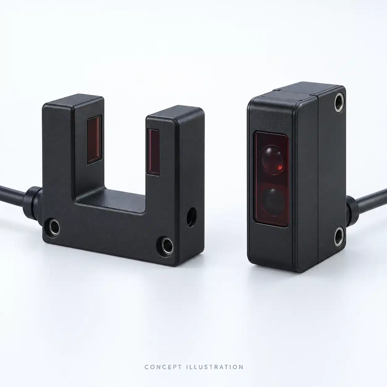
The practical question is not which sensor looks smaller or has the longest advertised range. It is which arrangement can keep the required target-present and target-absent states distinct. First eliminate unsuitable mounting arrangements, then challenge the remaining choice with the most difficult targets, background, and operating speed.
Quick Comparison: Slot vs Diffuse Photoelectric Sensors
Use the following comparison to select an arrangement worth testing, before comparing individual models.
| Selection question | Slot photoelectric sensor | Conventional diffuse photoelectric sensor |
|---|---|---|
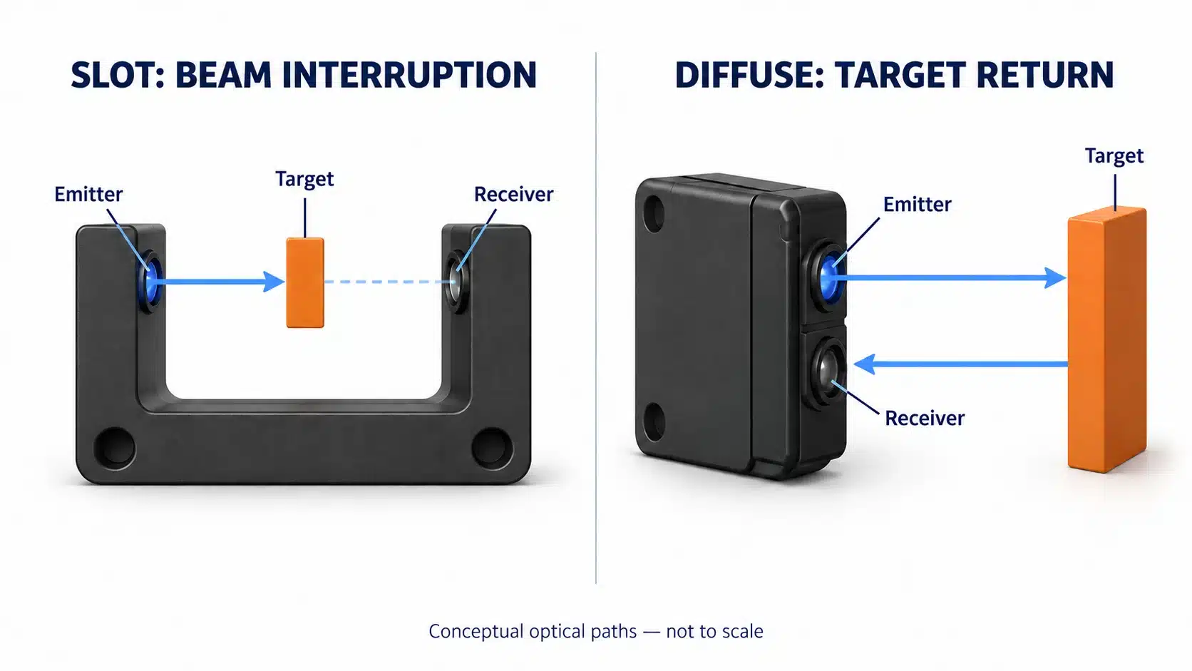
| What creates detection? | The target interrupts light between opposed optics within the fork. | The target returns emitted light to a receiver in the same housing. |
| What access is needed? | The relevant feature must enter the opening and cross the beam without collision. | The sensor needs a clear view of the target from one side. |
| Which target properties matter most? | Beam coverage, opacity, feature size, and the permitted path through the slot. | Returned light, affected by surface, angle, size, and distance. |
| What can confuse the empty state? | An unintended obstruction or contamination in the fixed light path. | Light returned by the background or nearby machine parts. |
| What mechanical limit comes first? | Slot width, usable depth, and the moving assembly's full clearance envelope. | Available mounting position, viewing angle, and target-to-background arrangement. |
| How should speed be compared? | Check operation and release timing, the smallest target and gap, and input capture. | Apply the same checks; housing shape and sensing mode do not establish a count rate. |
Background suppression is a distinct reflective option to evaluate when ordinary diffuse sensing cannot adequately separate the target from the background. It should not be assumed to be a feature of every diffuse sensor.
How Slot and Diffuse Sensors Detect Targets Differently
Slot Sensors: Fixed Beam Interruption Detection
In an optical slot sensor, the emitter and receiver face each other across the opening. With the path clear, light reaches the receiver. An object crossing that path reduces the received light, allowing the electronics to change the output state. The fork holds the two optical sides in a fixed relationship, but the machine still has to position the target correctly.
This arrangement can detect an opaque feature without depending on light reflected from its surface. A glossy or dark finish therefore presents a different problem from the same finish in reflective detection: the first question is whether the feature interrupts enough of the beam. A target passing above the optical axis, or a transparent target transmitting too much light, can defeat that assumption. The physical opening alone says nothing about whether the required feature will be detected.
Diffuse Sensors: Reflection-Based Detection
A diffuse sensor sends light toward the object and receives some of the light that comes back. The target itself provides the return; a separate reflector is not required. Because the emitter and receiver share one housing, the sensor can observe a target from beside or above the process without surrounding it with a fork. This solves an access problem, but it makes the target's optical return part of the detection requirement.
For ordinary intensity-based diffuse sensing, the electronics evaluate the received light against a switching threshold. The setting must detect the weakest acceptable target return while rejecting the strongest return with the target absent. If those conditions overlap, a setting that works for one sample may fail on another. The useful test is therefore a comparison of both states across the intended product range, not simply a demonstration that the sensor can detect an object.
Compare the Detection Conditions That Matter
Target Path, Clearance, and Detection Feature
Define the event before sizing the sensor. Detecting an entire workpiece, detecting a small tab on that workpiece, and counting successive tabs are different tasks. Identify the feature that must cause the state change and the range of positions it can occupy. Otherwise, a demonstration may detect a larger adjacent surface while leaving the actual requirement untested.
For a fork arrangement, draw the complete movement through the opening, including sideways movement and tilt. Check that the required feature crosses the optical axis at every permitted position and that the rest of the assembly clears the housing. Slot width and penetration depth describe the available space; minimum detectable object describes optical capability under specified conditions. A target can fit inside the opening yet miss or only partly cover the beam. Check mechanical clearance from the drawing and detection capability from the sensing specification, then verify both with the actual moving feature.
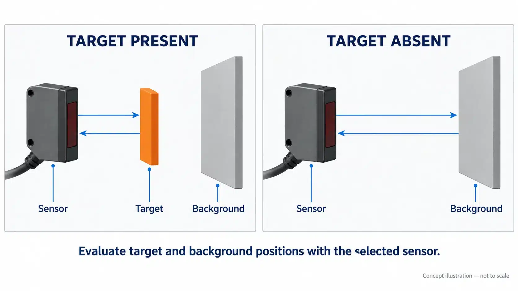
For diffuse sensing, identify what the sensor observes as the target shifts. If a small feature moves out of the sensing area and exposes the surrounding part or fixture, that surface may still return enough light to maintain the same output. The sensor would then confirm the assembly's presence without confirming the feature. A smaller light spot may help isolate it, but spot size alone does not prove minimum detectable target size or reliable switching. Test the feature-present and feature-missing conditions at the permitted position extremes.
Surface Variation and Background Influence
Evaluate surface and background together. A matte, light-colored sample facing the sensor may be easy to detect, but it may not represent the darkest, smallest, or most tilted acceptable part. A shiny surface can direct a strong reflection away from the receiver. Color is therefore one influence, not a complete selection rule.
Remove the target and repeat the check with the actual belt, bracket, tooling, or other visible background. Raising sensitivity to detect a weak target can also make the background trigger the sensor. If one intended setting cannot detect the difficult target and reject the empty background, further adjustment is not a dependable solution. Change the viewing geometry or evaluate a sensing method that creates a clearer distinction. For a separated background, that may mean background suppression.
For a slot sensor, the corresponding concern is what happens inside the beam path. An opaque target with variable paint color may still interrupt it consistently, but holes, translucent regions, or partial coverage can alter the result. Compare the actual detection feature, rather than treating all parts of the same outside dimensions as optically equivalent.
Installation Space and Machine Layout
An arrangement that works on a bench may be impossible to maintain on the machine. For a slot sensor, allow space for both arms, the mounting fasteners, the cable or connector, and removal of the sensor. Consider the moving assembly beyond its nominal centerline. A slightly wider fork may solve a clearance problem, but it does not automatically improve detection of a smaller feature.
For diffuse sensing, reserve a stable mounting position with an unobstructed view. Check where the beam points when a bracket shifts or the product position changes. A mounting adjustment that improves target return can also bring a machine surface into view; assess both states again after changing the angle.
Include access to the optical surfaces in either layout. Dust or residue can reduce received light. When the normal signal is only just sufficient to switch, that loss can turn a clean-bench success into intermittent detection. Leave room for inspection and cleaning, and qualify the arrangement under the contamination conditions expected between cleaning intervals. Moving closer or increasing sensitivity is not a universal cure: any change must still preserve the distinction between the required target and the empty state.
When a Slot Sensor Is the Better Starting Point
A slot sensor is a strong starting point when the machine already constrains an opaque feature to a repeatable crossing and has room for the fork. In that situation, the detection event can be based on obstruction rather than a consistent reflected signal. The mechanical guidance is part of the reason the choice works, not a detail to check afterward.
Applications Where Slot Sensors Provide More Stable Detection
A flag on a guided slide, an edge in a controlled channel, or separated opaque features crossing a fixed point can suit a slot arrangement. These examples share a useful condition: the mechanics establish where the beam will be interrupted. With adequate beam coverage and a clear interval between events, detection need not depend on a consistent surface reflection. That is why a fork can be a better starting point for these tasks; the advantage comes from the complete arrangement, not from the housing shape alone.
Test the smallest acceptable feature at the extremes of its permitted path before evaluating speed. If detection is intermittent even during a slow crossing, determine whether the feature misses the beam, covers too little of it, or transmits too much light. A higher switching-frequency rating does not correct any of those optical or geometric problems. If the moving assembly cannot clear the fork reliably, reconsider the arrangement before committing to the bracket design.
Transparent materials and features that only skim the beam need specific evaluation. Do not extend the opaque-target argument to them or treat every fork-shaped device as having the same sensing technology.
When Diffuse Sensing Fits Better—and When Background Suppression Is Needed
One-Sided Access and Larger Targets
Diffuse sensing is often the more practical arrangement when a sensor can be installed beside or above the detection point but a fork would obstruct the process. A larger object may also offer a usable reflecting area while being unable to enter a slot. The reason to begin here is access and geometry; reliable reflection still has to be established.
For an overhead container-detection task, identify which surface should create the signal and what replaces that surface in the sensor's view when the container is absent. Container-height changes alter the sensing distance and may change the area observed. Compare the acceptable height, finish, and position extremes with the empty conveyor at the same intended setting. Detecting the nearest, brightest sample alone does not establish that the installation can distinguish the complete product range from the background.
Ordinary diffuse sensing remains a reasonable candidate when the acceptable targets and the background produce sufficiently distinct returns over the required positions. Where that distinction disappears, reconsider the optical arrangement instead of selecting a model solely for greater advertised range.
What Background Suppression Changes—and What It Does Not
Background suppression, or BGS, adds distance discrimination to reflective sensing. A common implementation uses triangulation: the position of the returned light on the receiver changes with object distance. The sensor can use this geometric information to distinguish a target in its sensing region from a farther background, rather than deciding from returned intensity alone.
This changes the selection question. Instead of asking only whether the target is brighter than the background, examine where both can be relative to the sensor and the sensing boundary. BGS deserves consideration when a visible background can trigger ordinary diffuse detection and there is useful distance separation. Moving the sensor or background, changing the viewing angle, or evaluating another optical method can also be valid responses; BGS is not the only possible remedy.
BGS still needs a usable optical return and a suitable separation between the target and background positions. A highly tilted reflective surface may return too little light, while a target close to the sensing boundary can leave little margin for movement. Check the selected model's target conditions, sensing limits, and required separation; do not treat a nominal cutoff as a perfect boundary for every material. Test the farthest acceptable target and the nearest background before accepting the setting. Turning down ordinary diffuse sensitivity is not equivalent: it changes the response to light level rather than adding distance discrimination.
Check Speed, Switching Logic, and Controller Compatibility
Response Time vs Switching Frequency
Response time describes the delay between an optical change and the corresponding output change. Operation and release can have different limits, so check both. Switching frequency describes repeated operation under specified test conditions; it cannot be substituted directly for either delay. A frequency rating alone does not tell you whether the shortest feature and the shortest gap in your machine will each produce a usable electrical state.
For counting, examine the shortest target event and the shortest gap at the highest required passage speed. A sensor may recognize each target yet fail to return to the other state before the next one arrives. The output then merges successive events, and the controller cannot count them separately. Check feature size, spacing, and beam crossing position together with the model's operation and release specifications; use the actual output waveform to resolve borderline timing.
The receiving device introduces another requirement. A programmable logic controller (PLC) must capture the output pulse using its actual input configuration. A sensor indicator changing state does not establish that the controller has registered the event. Check the input's documented filtering and capture behavior, then compare the controller's observed events with a known reference count at operating speed. This system test applies to both sensor arrangements.
NPN/PNP and Light/Dark Operation
NPN and PNP describe electrical output arrangements. In common DC transistor-output circuits, an NPN output sinks current through a load connected toward the positive supply; a PNP output sources current through a load connected toward the negative supply. Match that arrangement to the receiving input and its common connection, then check the exact model's supply, output, and load ratings. A matching connector does not establish compatibility, and changing software logic cannot correct an incompatible electrical circuit. Use the documented wiring diagram rather than an assumed pinout or wire color.
Light-ON and Dark-ON specify which received-light condition activates the output. They do not select NPN or PNP. With an opaque target in a typical slot arrangement, target presence reduces received light; in ordinary diffuse detection, it increases the return. The desired target-present output can therefore require different light/dark settings even when the electrical output type stays the same. Define the required controller state for both target present and target absent, then confirm those states using the actual model's truth table and installed input.
Validate the Sensor Choice Before Ordering
Test Worst-Case Detection Conditions
Use a planned comparison that can disqualify a weak candidate, rather than a demonstration designed to make it switch. Follow the machine's safe commissioning procedure; arrange mechanical and electrical changes with hazardous motion and relevant power isolated before controlled operation.
- Define the required event and its reference. Specify whether the system must recognize presence, an edge, or each separate part. Establish how correct events will be counted or checked independently.
- Assemble the difficult but acceptable samples. Include minimum features, relevant finishes, translucency where applicable, and the permitted position and angle extremes. Select them because they challenge the optical mechanism, not simply because they are convenient to obtain.
- Test the absent state as deliberately as the present state. For the slot arrangement, check the clear path and possible unintended obstructions. For diffuse sensing, include the actual background at its closest or strongest-return condition.
- Run the extremes using one intended operating setup. Confirm that detecting the difficult sample does not create false detections with no target. For BGS, include both the target and background position limits. Record any setting changes rather than hiding them between trials.
- Verify dynamic behavior through the receiving input. Use the required speed range and shortest gap, then compare the recognized events with the reference. Investigate missed or extra events at the optical, sensor-output, and input-capture stages separately.
- Retain the accepted configuration and boundaries. Record the model and output option, mounting dimensions, settings, samples, background, speed, input configuration, and observed results. Include the intended cleaning and recheck conditions. If a requirement is not met, change the arrangement or candidate and repeat the affected tests.
These are recommended acceptance steps, not a report of XSZ test results. Agree on the application's acceptance criteria before using the observations to release a design.
Information Needed for Model Selection
Provide enough information for a supplier to assess the complete detection point:
- Required event and samples: identify what must be detected and what must not; include the smallest relevant feature and representative material and surface variations.
- Movement and space: provide a sketch of the target path, its tolerances, available mounting space, and the sensor-to-target and target-to-background positions.
- Timing requirements: state speed variation, minimum spacing, and whether the system needs presence detection, edge recognition, or counting.
- Electrical interface: identify the supply, receiving input, required active state, and connection constraints so the actual ordered output can be checked.
- Operating and acceptance conditions: describe lighting, contamination, cleaning, and temperature exposure relevant to the installation, together with how acceptable detection will be verified.
A dimensioned sketch and difficult samples can resolve questions that a request for “a slot sensor” or “a diffuse sensor with a longer range” leaves unanswered. Keep model-specific ratings distinct from the conditions that your application needs to pass.
Practical Advice From an Automation Sensor Manufacturer
Ask the supplier to review the detection point before choosing a catalogue model. The proposal should explain how the optical arrangement separates the required states, whether the mounting drawing accommodates the full movement, and how the output matches the receiving input. Keep unsupported requirements open for documentation or sample verification. A useful recommendation identifies what would rule a model out, not just a nominal range that appears to fit.
When discussing a candidate with XSZ, use the same target samples, installation sketch, and input requirements that will govern acceptance. Confirm the exact ordering configuration and keep the accepted setup with the machine documentation. If a replacement changes the optical method, output option, or settings, check the affected conditions again. A matching housing or nominal distance is not enough to establish interchangeability.
FAQ
Is a laser sensor a separate alternative to slot and diffuse sensing?
No. Laser describes a light-source option; slot and diffuse describe sensing arrangements. Laser versions exist within both categories. Decide first whether the task is better served by beam interruption or returned light, then assess the selected model's beam characteristics and switching performance. The word “laser” alone does not establish the required target resolution or application fit.
Can either sensor count parts that touch each other?
Only if the detection point produces distinguishable events for those parts. If touching objects keep a single switching sensor continuously in the same state, faster response cannot create separate count pulses. A contour, opening, or other detectable feature may provide transitions even without physical separation. Test that feature; otherwise, introduce spacing or evaluate a different sensing arrangement. Do not infer countability from presence detection alone.
Technical Resources
- OMRON — Overview of Photoelectric Sensors: optical paths, reflective sensing, and distance discrimination.
- OMRON — Explanation of Terms: response time, operating logic, and sensing conditions.
- ifm — Photoelectric Sensor Technology Overview: target and background influences and background suppression.
- Baumer — OG010U.I-GW1O.7WL Technical Data: an example of separate optical, timing, and mechanical specification fields; its values are not XSZ specifications.
- Banner Engineering — What Is Excess Gain and How to Use It to Choose a Sensor: optical signal margin and contamination.
- OMRON — NPN and PNP Transistor Outputs: the common output and load arrangements discussed above.
- Balluff — From Diffuse to Through-Beam: Understanding Photoelectric Sensor Types: laser light-source options within diffuse and fork sensing.